Same thing with my blend balance
Shadoweclipse13's Master Schematic Page!
-
ludobag1
- PAT. # 2.972.923

- Posts: 2547
- Joined: Sun Nov 23, 2008 4:28 pm
- Location: france
Re: Shadoweclipse13's Master Schematic Page!
My 2 cents , always trust your multimeter and before mount in circuit ,i have thé same things with my 4p 3p ,hopefully i have a second one who works flawless ,the first one have a trouble ans as i remember not what it was if i have test it before soldering it i have avoid lot of headach 
Same thing with my blend balance
Same thing with my blend balance
-
gibs

- PAT. # 2.972.923
- Posts: 280
- Joined: Mon Aug 01, 2011 5:03 pm
- Contact:
Re: Shadoweclipse13's Master Schematic Page!
Getting ready to make an attempt at my wiring mod with 2 S1 switches. I’m just gonna wire up the one to add a 50k resistor between the input and ground lugs to simulate a 50k tone control on the lead circuit, keeping the rhythm circuit stock, will probably set it up to swap capacitors out on the lead channel for when the S1 is engaged to better suite the darker tone.
I will say that this talk with the 4way rotary switch has me thinking of a wiring idea I have. I have a dream to make an electric VI with JM trem setup, I was gonna just got with a 3 way toggle, and 2 more S1 switches for series/parallel and my pseudo rhythm circuit idea. But now I’m wondering if I could do something with multi pole rotary switch and s1 and some Curtis Novak electric XII pickups.
So here’s the idea:
S1 off:
1. Bridge pickup
2. Bridge and neck parallel
3. Bridge and neck series
4. Neck pickup
S1 on:
1. Bridge pickup
2. Bridge treble side coil and neck bass side coil in parallel
3. Bridge bass side coil and neck treble side coil in parallel
4. Neck pickup
Could possibly do series variation in positions 1 and 4 when the switch is active, but it’s already a pretty complicated layout so would probably be pushing it already.
Sound possible, or just way too complicated?
-
bigugly

- PAT PEND

- Posts: 20
- Joined: Tue Jan 06, 2015 1:51 pm
Re: Shadoweclipse13's Master Schematic Page!
Spent another night soldering and...No dice (cue sad trombone)bigugly wrote: ↑Mon Jan 10, 2022 11:40 amI may have figured out why this isn't working.
I believe my original diagram makes the following assumption about the layout of the different sections of the rotary switch:
I finally busted out the multimeter last night and found that the switches I'm working with actually work like this:
Going to re-solder it up tonight to see if it works...
Back to the drawing board - I sat down and really traced out what I'm trying to do.
Everything checked out comparing the rotary-equivalent functions compared to the original slide switch and 3 way toggle in the original circuit. Knowing that, I went back and double checked my connections. Lo and behold, I managed to spot one connection error I had made.
So, the good news is that I can confirm that my original diagram does work.
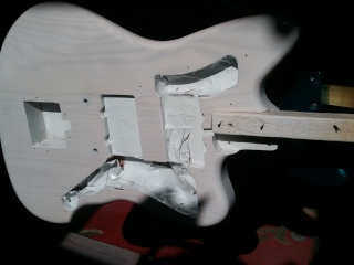
The bad news is that it appears my neck pickup got damaged somewhere along the way in this adventure. This Van Leeuwen JM has shielding plates in the pickup cavities. They fit pretty tight and the neck one got stuck when I was removing the neck pickup and gave the ground lead a good yank, most likely damaging it. Going to try to repair this evening, but if I can't, I'll have to swap it out. The end is in sight!
-
Paul_Valentine

- PAT PEND
- Posts: 38
- Joined: Tue Apr 06, 2021 8:51 am
Re: Shadoweclipse13's Master Schematic Page!
Hi, I already posted it in the topic I made for the project (here) but this topic is more focused on schematics. So, hope to find help here.
Can someone confirm if this schematic is correct, please? I would like to know before soldering it. As it helps me to be more confident putting it together and about result.

I draw this schematic mostly by coping parts of existing diagrams and by using (little) knowledge I have about guitar electronic. I could simply overlooked or misinterpreted something.
This is list of functions which electronics should perform:
- series/parallel switch - copied from schematic promising no dead position on pickup selector
- Fender TBX Tone Control - wired as dual gang tone control. First side the 1Meg linear one wired as Jag tone control. Second side wired as Rhythm circuit simulation. Center position is dented and should works as "no load". There is also separate diagram for this since it's bit wild. Both sides have resistor wired in parallel. The 56k one is taken from Jags tone control. 2nd resistor has function to drop pot from 250k to 50k and the its value is calculated by using resistence calculator.
- 1M volume pot with push/pull switch. It suppose to be on/off for Behind the Bridge pickup. It is placed after volume to be independent on other pickups. Something like 2nd circuit
- the 3rd circuit with piezo disc and its switch
Parts where I'm not 100% sure:
- Series/Parallel switching
- tone control wiring - Jags and rhythm circuit are wired different than majority of guitars + I'm not sure if my wiring of dual gang pot will work
- piezo disc circuit wired in parallel to main circuit soldered directly to jack
Can someone confirm if this schematic is correct, please? I would like to know before soldering it. As it helps me to be more confident putting it together and about result.
I draw this schematic mostly by coping parts of existing diagrams and by using (little) knowledge I have about guitar electronic. I could simply overlooked or misinterpreted something.
This is list of functions which electronics should perform:
- series/parallel switch - copied from schematic promising no dead position on pickup selector
- Fender TBX Tone Control - wired as dual gang tone control. First side the 1Meg linear one wired as Jag tone control. Second side wired as Rhythm circuit simulation. Center position is dented and should works as "no load". There is also separate diagram for this since it's bit wild. Both sides have resistor wired in parallel. The 56k one is taken from Jags tone control. 2nd resistor has function to drop pot from 250k to 50k and the its value is calculated by using resistence calculator.
- 1M volume pot with push/pull switch. It suppose to be on/off for Behind the Bridge pickup. It is placed after volume to be independent on other pickups. Something like 2nd circuit
- the 3rd circuit with piezo disc and its switch
Parts where I'm not 100% sure:
- Series/Parallel switching
- tone control wiring - Jags and rhythm circuit are wired different than majority of guitars + I'm not sure if my wiring of dual gang pot will work
- piezo disc circuit wired in parallel to main circuit soldered directly to jack
My offsets are Parts lefty Jaguar, Super Sonic and DIY Mandocello
-
gibs
- PAT. # 2.972.923
- Posts: 280
- Joined: Mon Aug 01, 2011 5:03 pm
- Contact:
Re: Shadoweclipse13's Master Schematic Page!
Not sure about the series/parallel, never seen one that didn’t dropout unless it used a 3pdt. The kill switch will not work, you need to place that between your output and the output of the volume control, wired so that when the switch is engaged that it connects the signal to ground.
-
Paul_Valentine
- PAT PEND
- Posts: 38
- Joined: Tue Apr 06, 2021 8:51 am
Re: Shadoweclipse13's Master Schematic Page!
Thank you for feedback. I have to admit I tried this way of wiring killswitch once in another guitar. The guitar became really noisy. So, I disengaged it from the circuit. I thought it is because the switch wasn’t grounded and it wasn’t shielded properly. But it isn’t the way it should be wired.gibs wrote: ↑Sun Jan 16, 2022 11:49 amNot sure about the series/parallel, never seen one that didn’t dropout unless it used a 3pdt. The kill switch will not work, you need to place that between your output and the output of the volume control, wired so that when the switch is engaged that it connects the signal to ground.
My offsets are Parts lefty Jaguar, Super Sonic and DIY Mandocello
-
Shadoweclipse13

- PAT. # 2.972.923
- Posts: 12445
- Joined: Fri Feb 07, 2014 9:22 pm
- Location: Stuck in the dimension of imagination
Re: Shadoweclipse13's Master Schematic Page!
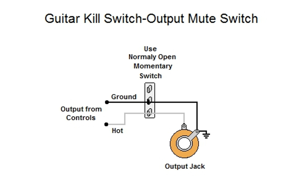
This is how I usually wire kill switches. The noise isn't an issue, and it definitely works. Just make sure that it's a normally-open momentary switch and you won't have an issue.
Pickup Switching Mad Scientist
http://www.offsetguitars.com/forums/viewtopic.php?f=8&t=104282&p=1438384#p1438384
http://www.offsetguitars.com/forums/viewtopic.php?f=8&t=104282&p=1438384#p1438384
-
JohnnyJaguar
- PAT PEND
- Posts: 6
- Joined: Tue Nov 26, 2019 11:36 am
Re: Shadoweclipse13's Master Schematic Page!
Hi,
I’m actually re building a Cobain jag that is in poor shape.
I plan to wire it as it was designed, plus adding a dpdt switch for serie/parallel, but I don’t know how to figure it…
Did someone make it before ?
Any help is more than welcome !
Thanks
Ps : this is t the schematic I’m going to use :
https://www.fmicassets.com/Damroot/Orig ... A_SISD.pdf
-
timtam

- PAT. # 2.972.923
- Posts: 2738
- Joined: Sun Oct 22, 2017 2:42 am
- Location: Melbourne
Re: Shadoweclipse13's Master Schematic Page!
Do you want to switch the Cobain's two Dimarzio HBs (Super Distortion and PAF) in series with each other ? You might want to wire it up with alligator clips first to see if you like that sound. Or instead do you want to switch the two coils of each HB to be in parallel in addition to stock series ?
This is how the somewhat complex stock Cobain control/switching circuit works (as in your linked stock wiring diagram) ...

This is how the somewhat complex stock Cobain control/switching circuit works (as in your linked stock wiring diagram) ...
"I just knew I wanted to make a sound that was the complete opposite of a Les Paul, and that’s pretty much a Jaguar." Rowland S. Howard.
-
JohnnyJaguar
- PAT PEND
- Posts: 6
- Joined: Tue Nov 26, 2019 11:36 am
Re: Shadoweclipse13's Master Schematic Page!
Thanks for your answer @timtam,
I have a dp100 with 4 cables, and dp103 with only 3, so I guess I can’t split the 103.
That’s a choice limiter isn’t it ?
I can only series/parallel both humbuckers if I’m right
In fact, in the cobain jag, it is missing a switch, and I have one spare that I can put in it.
So I’m looking what to do with it.
So if you guys have an other idea, be welcome to tell me !
-
timtam
- PAT. # 2.972.923
- Posts: 2738
- Joined: Sun Oct 22, 2017 2:42 am
- Location: Melbourne
Re: Shadoweclipse13's Master Schematic Page!
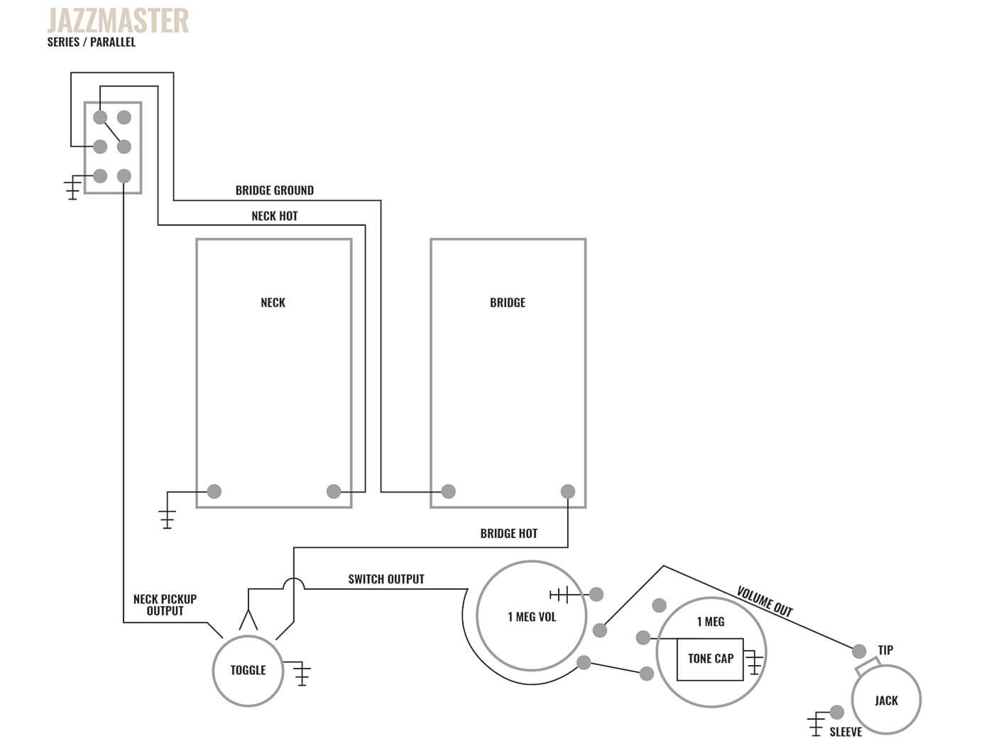
For the two HBs in series option, you would insert the series/parallel switching method for the re-purposed rhythm switch by Mike Adams (Puisheen) as below ... but instead using your added DPDT switch (2 position only, no centre position), since you want to keep the rhythm circuit. Insert the new switch before the volume pots/3-way toggle in the schematic above. Following the diagram below, the bridge pickup's coil ground and neck's hot would go to the new switch.
https://guitar.com/guides/diy-workshop/ ... t-guitars/
The "4 wire" Dimarzio bridge DP100 should have a bare shield (5th) wire as well, which should be the metal grounding wire (case/cover). In series, the normally-grounded coil side of one pickup (bridge here) is connected to the hot side of the other pickup (neck). So you don't want the coil ground and metal ground for that bridge pickup tied together like in other wiring schemes - because you don't want the series switch to also connect the metal ground of the bridge pickup to the neck's hot. The bridge's metal ground/shield instead needs to remain permanently grounded (to any convenient ground point).
Note that this DPDT series/parallel scheme has an added negative/positive feature, depending on your perspective. As you can see by looking at the DPDT switch in the diagram, when series mode is selected there (upper terminals on the DPDT), there is no connection being made to the 'neck pickup output' wire (going to the selector switch). So when you select the neck pickup (alone) with the pickup selector switch while in series mode, you will get no sound. So, like a 'kill switch' if you will, which some people may like (but may confuse others to think there's a wiring fault). If you don't like that, Rothstein suggested a modified version of the series/parallel scheme that uses a 3PDT switch instead of the DPDT to get around that issue. It's the "3PDT" diagram at the link below. You would wire it to use the 3rd switch pole to link the neck hot to the selector switch's neck terminal when in series mode.
https://www.guitar-mod.com/rg_jazzmaster_stb.html
"I just knew I wanted to make a sound that was the complete opposite of a Les Paul, and that’s pretty much a Jaguar." Rowland S. Howard.
-
WilburBufferson

- PAT. # 2.972.923
- Posts: 58
- Joined: Wed May 14, 2014 4:41 am
Re: Shadoweclipse13's Master Schematic Page!
I searched this thread but couldn't find it (forgive me if I missed it). I have a duo sonic and want 2 push-pulls: one for series, one for out of phase. Modifying the diagram below (removing the "solo" option), do I simply take the lead from the middle lug of the toggle and run it to the tip of the jack (and eliminate all the wires associated with the "solo" switch)?

-
Shadoweclipse13
- PAT. # 2.972.923
- Posts: 12445
- Joined: Fri Feb 07, 2014 9:22 pm
- Location: Stuck in the dimension of imagination
Re: Shadoweclipse13's Master Schematic Page!
Hey there!WilburBufferson wrote: ↑Wed Mar 30, 2022 4:57 amI searched this thread but couldn't find it (forgive me if I missed it). I have a duo sonic and want 2 push-pulls: one for series, one for out of phase. Modifying the diagram below (removing the "solo" option), do I simply take the lead from the middle lug of the toggle and run it to the tip of the jack (and eliminate all the wires associated with the "solo" switch)?
Do you not want the volume or tone pots either? If you want just series and phase switches with no volume or tone pots, you'd run the output of the 3-way switch (center lug, like you said) to the tip of the jack.
If you want everything except the solo switch (including the volume and tone) you'd take the same center lug form the 3-way toggle and run it to the bottom lug of the volume pot (where the top lug of the solo switch is connected to).
If that's too confusing, I could draw it up for you tonight as that would only take a couple seconds to modify an already existing schematic.
Pickup Switching Mad Scientist
http://www.offsetguitars.com/forums/viewtopic.php?f=8&t=104282&p=1438384#p1438384
http://www.offsetguitars.com/forums/viewtopic.php?f=8&t=104282&p=1438384#p1438384
-
WilburBufferson
- PAT. # 2.972.923
- Posts: 58
- Joined: Wed May 14, 2014 4:41 am
Re: Shadoweclipse13's Master Schematic Page!
[/quote]
Hey there!
Do you not want the volume or tone pots either? If you want just series and phase switches with no volume or tone pots, you'd run the output of the 3-way switch (center lug, like you said) to the tip of the jack.
If you want everything except the solo switch (including the volume and tone) you'd take the same center lug form the 3-way toggle and run it to the bottom lug of the volume pot (where the top lug of the solo switch is connected to).
If that's too confusing, I could draw it up for you tonight as that would only take a couple seconds to modify an already existing schematic.
[/quote]
Hey!! I do want the volume and tone pots, so I will do what you describe in the 2nd option -- thank you! I don't have push pulls for 250K pots, but I do have them for 500K. Should be okay? That's what the tone knob is for, right? BTW, this is a current Fender reissue, MIM Duo Sonic, with the original single coils (which I like).
-
Shadoweclipse13
- PAT. # 2.972.923
- Posts: 12445
- Joined: Fri Feb 07, 2014 9:22 pm
- Location: Stuck in the dimension of imagination
Re: Shadoweclipse13's Master Schematic Page!
Pot size is personal preference, but a lot of people seem to prefer 250K with single coils. The tone knob only shunts treble frequencies to ground, and with passive electronics, can't ever add any frequencies, only vary the amount that you take away. If the 500K pots are too bright, technically, that might work. If you've already got them, it's worth a shot. You could always swap them out later if you don't like them. He'll, you might discover a really awesome sound you didn't know you could get!WilburBufferson wrote: ↑Wed Mar 30, 2022 5:54 amHey!! I do want the volume and tone pots, so I will do what you describe in the 2nd option -- thank you! I don't have push pulls for 250K pots, but I do have them for 500K. Should be okay? That's what the tone knob is for, right? BTW, this is a current Fender reissue, MIM Duo Sonic, with the original single coils (which I like).
Pickup Switching Mad Scientist
http://www.offsetguitars.com/forums/viewtopic.php?f=8&t=104282&p=1438384#p1438384
http://www.offsetguitars.com/forums/viewtopic.php?f=8&t=104282&p=1438384#p1438384