.
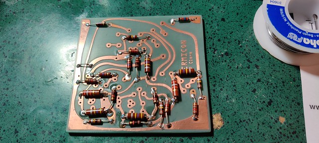
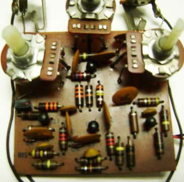
..... the parts are on the wrong side of the board. They go on the un-traced side, leads poke through to the trace side, and then are soldered.
Verify any can-type caps have the + side to the correct voltage and diodes are not reversed. Open up any pedal you currently have and see how it's soldered.
You see the traces here but that is just read through on the board.

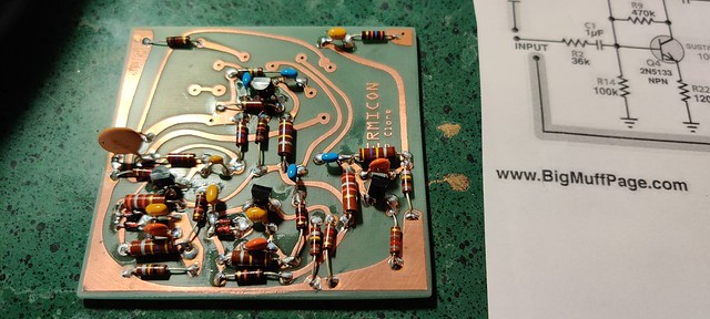
Most circuit problems are solder blobs bridging, wrong parts in the wrong place, overheated and cooked parts (which soldering on the same side as the parts can do), or cold solder joints. Check that the pots are wired so you have 'max' when you think you do (check the full range).
You can disconnect the output hot wire from the board and then with a looper pedal playing some input you should be able to probe through the stages on the board with the output wire to see where there is or is not signal. Don't use your best amp and don't have the volume up too loud.
.


 IMG_20200605_104213 by Christopher Louck, on Flickr
 IMG_20200605_104401 by Christopher Louck, on Flickr
 IMG_20200605_114325 by Christopher Louck, on Flickr
 IMG_20200605_104152 by Christopher Louck, on Flickr
 IMG_20200605_114332 by Christopher Louck, on Flickr
 IMG_20200605_114357 by Christopher Louck, on Flickr