Ampeg B15 rebuild

Make it loud here.
User avatar
øøøøøøø
PAT. # 2.972.923
PAT. # 2.972.923
Posts: 5996
Joined: Sun Jan 06, 2008 8:26 pm
Location: Los Angeles
Contact:

Ampeg B15 rebuild

Post by øøøøøøø » Wed Dec 28, 2022 11:46 pm

Once in awhile I have to play bass on something myself. I always had an Ampeg B-25B and a Weber 15" in an old cab that was fine.

The other day I got a very good deal on an RE-101 Space Echo and an Ampeg B-15N, both needing work. The Space Echo fixed right up--it just had some pots and switch contacts that needed cleaning and lubricating. So that was a win.

The B-15N was even more of a mess than I expected though, so it all evened out. This is a work in progress (I'm linking to pics hosted on a social media site, so hopefully they don't disappear).

Image

As it arrived. I'm not a B-15 expert yet, but I think this is either a single baffle cab thats been highly worked over or someone's homemade reproduction that fits the original chassis tray. All logos missing, no ports on baffle (hinting that it's a replacement), covering looks like Fender Blond-era Nubtex that's been painted black with brush-on enamel.

There's a hole inside the cabinet; you can see a substantial amount of daylight through the bottom left corner.

Most hardware is either damaged or missing, with a mashup of cross-threaded incorrect screws of various sizes and thread pitches holding on what remains. An incorrect-looking metal plate holds a quarter-inch jack on the left side.

Nice Eminence Delta 15 speaker installed, though--a very good B-15 speaker that's not worlds apart from the original CTS sonically (a bit more low-end extension, perhaps).

A repro double-baffle cab from Fliptops is the way; this one looks destined either for "free local pickup" or the trash.

Image

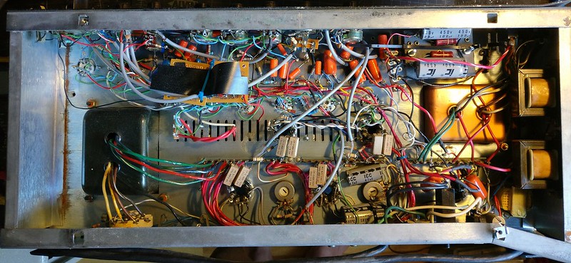
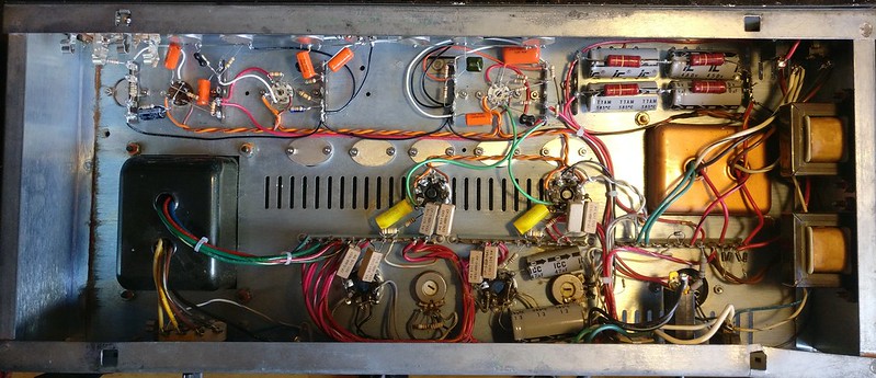
Inside is worse than I'd hoped. It's hard to parse what's even going on here--a real nightmare of amateurish work and sloppy bodge jobs. The first filter cap is literally electrical-taped to the wall of the chassis.

Underneath all of that, it looks like a mashup of parts from various eras.

It has the fixed-bias circuit, as the single-baffle cab would imply. But it's built out on an earlier-style eyelet board, with solder-lug tube sockets that are clearly original and riveted to the chassis in correct fashion. Chassis side pieces are plywood, which only happened before '64... so a lot of things don't really line up here.

Later-style PCB sub-assemblies hold the front panel controls... but the pots themselves are from the mid-1970s (a mix of Clarostat and CTS parts... most of the latter with incorrect splined shafts and solder lugs; clearly not factory).

The original 2-prong power cable remains; the speaker cable has been terminated with a quarter-inch connector (should be 4-pin XLR or octal)

Ground polarity switch is black instead of nickel. My working theory is that someone had two B-15s, took the best parts from each (in their estimation), and left the rest for dead... either got it barely-working, or left it to get trash-picked in the 70s or 80s by someone with DIY aspirations

User avatar
øøøøøøø
PAT. # 2.972.923
PAT. # 2.972.923
Posts: 5996
Joined: Sun Jan 06, 2008 8:26 pm
Location: Los Angeles
Contact:

Re: Ampeg B15 rebuild

Post by øøøøøøø » Wed Dec 28, 2022 11:53 pm

Image

It's a struggle to imagine someone's reasoning for spraying silicone everywhere. Whoever did this work was either inexperienced, in a complete rush, very frustrated, not-very-knowledgeable, or all of the above.

You can see that the dropping resistors in the B+ supply have been made by using multiple parts in series and parallel to derive the correct resistance values. Likewise for the bias supply filter capacitor (two caps in parallel). This whole side of the board is clearly modified and unoriginal.

The first filter cap is literally held to the side of the chassis with electrical tape--pretty unsafe. Most wiring has been messed with... numerous splices, cuts, melted ends... a mix of wire from 24ga solid up through 18ga stranded and everywhere in between.

Image

Cold solder joints everywhere, and wire that was clearly nicked when stripping (multiple wires just break off at the joint with the slightest pull)

Miraculously, it worked and sounded okay when I got it, but was a bit noisy.

Image

This is interesting... I hadn't noticed that the amp was running EL34/6CA7s. Nice tubes, but the wrong kind of nice tube for an Ampeg B-15.

Maybe this has something to do with the earlier-spec eyelet board being set up for fixed bias? Maybe someone started with an NC and converted it to NF to run EL34s (which barely makes any more sense, in truth).

Or maybe they had an NC and didn't realize it, and were working from an NF schematic?

Of course, neither scenario would explain the single-baffle cab (unless the cab was also modified?) or the PCB control board sub-assemblies.

These nice 6CA7/EL34s are good and strong; I'll probably stick them in the Orange that's sitting behind the B15 in the first pic (it still has the JJs it shipped with).

Image

It didn't take long to decide that the only way to handle this is with a full teardown and rebuild. It just wouldn't be reliable enough otherwise... there's no patching up a bad patch job. It'd be more work in the end, and there would always be one more issue I'd missed somehow.

You can see that the input side of the board looks somewhat original, and like it may have come from an earlier B-15 revision. Cornell-Dubilier "Greenies" in place, and layout matching other photos I've seen.

Further into the amp, things start to look highly suspect. Slightly-incorrect parts values and vendors... the tubular axial caps are actually very nice parts, military CP05 (vitamin Q) hermetic paper-in-oil with the glass end seals.

Further left, the power supply and bias supply are obviously reworked. I'm not sure I've ever seen evidence that a B-15NF was ever built on an eyelet board like this one, but earlier revisions were built on boards exactly like this.

The 1970s solder-lug pots are bodged onto the PCB sub-assemblies with small bits of braided wire. They're not very structural, but they are nice parts. I considered reusing them until one fell apart in my hand due to metal fatigue (it probably got yanked around a lot by whoever was in here hacking away). The rest will get set aside... they'd probably be good volume pots in a 70s JM!

Original PC couplates are still in place and look undisturbed. All the shielded runs are properly terminated (shield grounded only on one end) and consistent with original appearance.

User avatar
øøøøøøø
PAT. # 2.972.923
PAT. # 2.972.923
Posts: 5996
Joined: Sun Jan 06, 2008 8:26 pm
Location: Los Angeles
Contact:

Re: Ampeg B15 rebuild

Post by øøøøøøø » Thu Dec 29, 2022 12:00 am

With the eyelet and control boards removed, it really shows just what kind of shape this thing was in.

I suspect the PT may be non-original, though it is fully potted in its enclosure with tar. The leads are cut very short and spliced. I haven't seen enough old B15s to know the entire range of shades of color for wire insulation, but these don't look incredibly like a lot of B15s I've seen. Still, it works, is properly potted in there and outputs the proper voltages (or thereabouts), so it can stay. It's clearly been in here for a very long time... probably since the 1970s or 1980s.

Image


This is after the first round of teardown and cleanup. The pilot lamp assembly doesn't look like pictures I've seen. The multi-section cap was a Nichicon that looked like it was probably from the 1980s; likewise for the two connected-in-series axial caps electrical-taped to the side of the chassis.

Someone spliced on random wire colors to the cut OT leads and surrounded them with a braided shield--it probably didn't do much.

Image

After a bit more cleanup of the chassis I started work on wiring the heaters in a more-sensible manner.

I learned in an Ampeg facebook group that the lack of serial number plus plywood sides dates the chassis itself to around 1960-1964. But the front panel has labels above the inputs, which was supposed to be a '66 feature? Since it's all one piece of bent metal I'm not sure how that could all be true, but this thing is full of contradictions.

Image

Thankfully, it seems like the output transformer is original (though perhaps not to this exact B15); just with cut leads and splices.

Image

Completed the 6V heater wiring--just need to connect the appropriate transformer secondary.

Before connecting the power transformer, I've got some new 18 AWG stranded wire coming that will make for nicer-looking splices. I'll pull the PT can again and execute the splices down inside the can so it looks better (needless vanity). I'll probably connect the transformer's 6V winding to the left-hand side of the pilot lamp assembly, since that's the shortest run.

The layout of the chassis (with pilot lamps in the middle) is slightly sub-optimal in terms of laying out heaters. You'll notice that on the 6L6 sockets (where the heater connections are on pins 2 and 7) the wires cross over the sockets instead of looping around. This is intentional, and important--going directly across the tube socket is likely to be quieter than creating anything resembling a "loop" of wire around the socket.

This isn't quite as crucial on the output tubes--fortunately the preamp 6SL7s are configured to have their heater pins of 7-8, which allows me to stay out of the way of the sensitive grid wires (inverse-square law is our friend here... the amount of radiated interference decreases with the square of distance).

Image

Tucking as much of the heater run as possible into the corner of the chassis will have a slight, but very real shielding effect. It will tend to draw some of the energy toward the chassis, away from the tube sockets.

When I run the ground connection for the hum balance pot, I'll likely run that 18AWG ground wire on top of the heater conductors to cast even more of a shadow in the interference.

The hum balance potentiometer at the end of the heater string serves as the "artificial center tap." It's a 100 ohm linear pot with a screw trimmer on the back, and serves to balance the heaters.

Each half of the heater winding connects to one end of the pot, and the center (wiper) will be connected to ground. Rotating the pot will help balance the heaters for least interference.

Balancing the heaters (splitting them into 3.15 volts on one, -3.15 volts on the other, with the ground reference in the "middle") has a few advantages.

First, the AC fields are only half as strong as the full 6.3V on one phase.

More importantly, the two halves are anti-phase and the energy will from each will want to cancel the other out if done correctly.

Just like common-mode rejection in balanced audio lines (e.g. XLR mic cable), the twisted pair helps ensure that at any given location, the radiated field from each wire will be in proximity to an opposite-polarity field that should cancel much of it out. The better the balance between the two anti-phase halves, the better the rejection of interference.

Why not use two tightly-matched 50 ohm resistors instead? Well it turns out that sometimes a slight imbalance in the resistance actually leads to the best radiated field balance! Theory and practice are often a little bit different, and this allows it to be fine-tuned for maximum rejection and quietest operation.

User avatar
øøøøøøø
PAT. # 2.972.923
PAT. # 2.972.923
Posts: 5996
Joined: Sun Jan 06, 2008 8:26 pm
Location: Los Angeles
Contact:

Re: Ampeg B15 rebuild

Post by øøøøøøø » Thu Dec 29, 2022 12:06 am

Image

Yanked a bunch of parts off the board. Almost everything was either incorrect, damaged, defective, worked-over, or in a non-sensible location.

Most of it went straight in the trash, but I did keep a few things aside.

Lots of this will probably end up in the trash as well, or at least not back in this amp... but the wirewound resistors are fine. The CP05 hermetic paper-in-oils are great (even if they don't end up back in this amp).

I want to do more research to see whether any of these might be original parts (even if so, most are probably too far gone to feel good about reusing)

Image

Left the C-D "Greenies" in place. They're original (or at least correct) and they're in the right locations on the eyelet board, so there was really no reason to disturb them. They're very nice parts that are getting harder to find, and there's little sense in putting them through another solder-desolder cycle stress.

The eyelet board itself was pretty disgusting--tons of solder flux residue around every eyelet, and the whole board covered in greasy film that had attracted dust.

The flux residue can worsen corrosion of parts, and the layer of grime can easily absorb moisture from the air and cause hard-to-troubleshoot issues by creating high-impedance leakage paths (especially close to the input). I've seen it happen. No need to take any chances... this will all get cleaned off.

Image

The input end of the board appeared warped and was kind of bent upward, floating in space.

Now I know why--the wooden spacer was crudely broken off.

It's obvious what happened--upon reassembly, the person who did all of this poor-quality work had forgotten to route the output transformer leads through the provided channels... so instead of disassembling to correct their mistake, they just grabbed something and broke off the part of the wood that was in the way.

I reattached what was left with some cyanoacrylate. You could make a case that I should've fabricated an entirely new wooden part, but my solution seems to keep the board flat enough (the wooden spacer was already crooked from the factory!) and this will be hidden once reassembled, so I'll just take the path of least resistance and keep it original.

Image

This is the eyelet board after a few more rounds of cleanup; pretty much ready to start rebuilding the amp once a few more parts arrive.

Scratches on the eyelet board near the mounting holes hint that someone may not have owned a nut driver, and were trying to hold the nut still with pliers or a flat-blade screwdriver instead.

Shipping is slow this time of year so progress will be slow as well, but I'll keep updating this here as long as the pics stay up.

User avatar
sal paradise
PAT. # 2.972.923
PAT. # 2.972.923
Posts: 3635
Joined: Thu May 27, 2021 12:41 am

Re: Ampeg B15 rebuild

Post by sal paradise » Thu Dec 29, 2022 12:08 am

Woah, this is really cool.

If I saw this, I wouldn’t know what to do
Image

To get it to this is amazing. You’ve reinvigorated my desire to start learning about amp building.
Image
I have nothing to offer anybody, except my own confusion?

User avatar
øøøøøøø
PAT. # 2.972.923
PAT. # 2.972.923
Posts: 5996
Joined: Sun Jan 06, 2008 8:26 pm
Location: Los Angeles
Contact:

Re: Ampeg B15 rebuild

Post by øøøøøøø » Thu Dec 29, 2022 12:24 am

sal paradise wrote:
Thu Dec 29, 2022 12:08 am
If I saw this, I wouldn’t know what to do
It does look pretty overwhelming--I felt that way for about 0.5 seconds and then it became clear that the only solution was a full gut-renovation. If it were a house instead of an amp, I've taken it back to the studs.

There are still a few things to decide.

I'm keeping the fixed bias circuit because I like it better, but putting most of the rest back to the earlier spec (including a repro of the fancier double-baffle cab. The original B-15 cab is kind of Ampeg's version of the Fender "tone ring" cabs. It was later simplified to cut costs).

But I could lay out the ground scheme in a way that, "on paper," should be a little quieter. Since this will mostly be a recording amp, there may be some value in that. But the original layout is also not really broken, and doing it my way might involve enlarging front panel holes to use isolating washers... maybe not the best/safest thing to do on an amp of this vintage? A slip of the drill could mar the faceplate pretty easily.

I could also just do a hybrid... a simple dual star-ground that doesn't bother to isolate the input jacks. I've got plenty of time to think it over.

User avatar
Shadoweclipse13
PAT. # 2.972.923
PAT. # 2.972.923
Posts: 12445
Joined: Fri Feb 07, 2014 9:22 pm
Location: Stuck in the dimension of imagination

Re: Ampeg B15 rebuild

Post by Shadoweclipse13 » Thu Dec 29, 2022 12:50 am

Awesome thread!!! This one is really interesting! I mean, all of your rebuilds are, but this one is a cool and weird find :P
øøøøøøø wrote:
Wed Dec 28, 2022 11:46 pm
I'm not a [insert any piece of gear here] expert yet
I think this is the epitome of you, Brad. I definitely appreciate your insights, expertise, and willingness to dive in and learn anything and everything. Watching this one!
Pickup Switching Mad Scientist
http://www.offsetguitars.com/forums/viewtopic.php?f=8&t=104282&p=1438384#p1438384

User avatar
Dr Tony Balls
PAT. # 2.972.923
PAT. # 2.972.923
Posts: 493
Joined: Thu Mar 12, 2015 10:05 am
Location: Brooklyn, NY
Contact:

Re: Ampeg B15 rebuild

Post by Dr Tony Balls » Thu Dec 29, 2022 6:44 am

Lookin good!
Instagram: thetonyballs

User avatar
ThePearDream
PAT. # 2.972.923
PAT. # 2.972.923
Posts: 2082
Joined: Sun Jun 25, 2017 6:18 am
Location: Detroit
Contact:

Re: Ampeg B15 rebuild

Post by ThePearDream » Thu Dec 29, 2022 8:04 am

Shadoweclipse13 wrote:
Thu Dec 29, 2022 12:50 am
Awesome thread!!! This one is really interesting! I mean, all of your rebuilds are, but this one is a cool and weird find :P
øøøøøøø wrote:
Wed Dec 28, 2022 11:46 pm
I'm not a [insert any piece of gear here] expert yet
I think this is the epitome of you, Brad. I definitely appreciate your insights, expertise, and willingness to dive in and learn anything and everything. Watching this one!

+1 to all this.

I also love to see neat wiring, methodically built up into a complex circuit. These types of posts do more to help me understand how amps work than anything else out there. They also inspire me to be more strategic in how I wire simpler things, like guitars .

Looking forward to seeing this progress!
Doug
@dpcannafax

User avatar
Jonesie
PAT. # 2.972.923
PAT. # 2.972.923
Posts: 4068
Joined: Sat Aug 09, 2008 7:00 am
Location: Massachusetts

Re: Ampeg B15 rebuild

Post by Jonesie » Thu Dec 29, 2022 8:48 am

Oh wow, that's really really cool. I had a B15 at the studio I used to work at. Really incredible sounding amp.

User avatar
Dr Tony Balls
PAT. # 2.972.923
PAT. # 2.972.923
Posts: 493
Joined: Thu Mar 12, 2015 10:05 am
Location: Brooklyn, NY
Contact:

Re: Ampeg B15 rebuild

Post by Dr Tony Balls » Thu Dec 29, 2022 9:42 am

Also this reminds me of the heavily monkeyed-with Sunn Model T that I restored a few years ago. Someone added SIX(!) preamp tubes in an attempt to add gain stages, reverb, maybe even tremolo but I cant remember. Thankfully the power amp section wasn't much messed with. As I got it:

Image

And after I returned it to stock:

Image
Instagram: thetonyballs

User avatar
øøøøøøø
PAT. # 2.972.923
PAT. # 2.972.923
Posts: 5996
Joined: Sun Jan 06, 2008 8:26 pm
Location: Los Angeles
Contact:

Re: Ampeg B15 rebuild

Post by øøøøøøø » Thu Dec 29, 2022 10:29 am

wow, yeah that was a mess

User avatar
hulakatt
PAT. # 2.972.923
PAT. # 2.972.923
Posts: 1064
Joined: Sat May 08, 2010 7:58 pm
Location: Pittsburgh

Re: Ampeg B15 rebuild

Post by hulakatt » Fri Dec 30, 2022 10:58 am

Dang. That was a horrid rat's nest when you cracked it. I'm really looking forward to it's resurrection!

I had an early B-15 at one point, not loud but glorious sounding amp! I have yet to play any other amp that sounded so fat, round and clean. BTW, they sound amazing with a Tele too ;)
She/Her

User avatar
øøøøøøø
PAT. # 2.972.923
PAT. # 2.972.923
Posts: 5996
Joined: Sun Jan 06, 2008 8:26 pm
Location: Los Angeles
Contact:

Re: Ampeg B15 rebuild

Post by øøøøøøø » Sat Dec 31, 2022 2:42 pm

Image

Decided to redo some of the dodgy splices on the two transformers. I still am not sure whether the transformers hidden in the tar potting compound are original Ampeg OEM parts, but at the very least the two transformers' potting looks substantially the same, whatever's in there is probably very old, and the amp definitely worked. So that's what I'm going with for now.

Most of the splices actually were just fine (if ugly), but it's good to know I've done them carefully and heat-shrink insulated them well. Most of the splices were able to be hidden down in the cans, so from the outside things are looking a lot less like a horror show now.

Image

I had to remove the input jacks to get to the OT mounting bolts, and those were a mess, too. There was evidence of at least three sets of resistors having been soldered onto these jacks and then cut off. The last set was tacked onto the surface in places. In other places the parts were almost tied in knots... super annoying to remove it all.

I used the resistors I had on hand... Dale CMF55 metal films, one old carbon film for the 2M2, and one generic metal film for the 5M6. I have zero reservations about using these "non-vintage-correct" parts; they'll work just fine. I had to remove the shielded wire from the "channel 1" jack assembly to untangle all the old cut-off resistor leads, so when I put it on I added a touch of heat shrink. Maybe I should've removed the other and done the same, but I've never seen such care taken on a vintage Ampeg and they all work just fine.

Image

The 1/4" extension speaker jack on these is configured in an interesting way--when an extension cab is plugged in, it's placed in series with the onboard speaker and the OT secondary is switched to a 16 ohm tap.

The downside is that with no extension speaker connected, all of the output goes through a leaf spring contact on the Switchcraft type 12 shorting jack. Corrosion on that switch contact is probably a certainty after this amount of time (you should've seen the amount of corrosion inside the chassis...) so I'm not taking any chances; it got replaced with a brand new part. As a result of the above-mentioned switching configuration, this jack must be isolated from the chassis using fiber shoulder washers.

With that, done, this chassis is just about ready to begin work.

Image

Still waiting on a couple of capacitors... one of the hermetic paper-in-oil CP05 (Vitamin Q) caps was actually leaking (presumably toxic, PCB-infested) oil. I've never seen one leak before. I stuck on some nitrile gloves, disposed of it in my hazardous-waste-collection bag, and cleaned the whole area very thoroughly. Then I ordered a couple more CP05s.

My pops used to say I "could tear up a steel ball" and that was definitely true of whoever had this amp before. Those caps were designed to be in literal war zones and not fail or leak.

I ran all jumpers under the board where possible... I just think it looks nicer that way.

Image

I created a jig to add 18 AWG solid-core legs to the panel-mount pots so I could attach them to the PCB. I wanted the leads to all be a uniform length so the sub-assemblies would sit closer to level on the front panel.

When soldering them to the board, I tried to keep things level (really I just eyeballed it; these things will bend a little if necessary) and then I clipped a test lead to each leg before soldering, as a heat sink. I didn't want to accidentally re-melt the lead-to-pot junctions and cause an inadvertent cold joint.

You can see one new run of shielded wire... this place was occupied by a bit of unshielded, yellow 18AWG stranded wire (with melted insulation on both ends when I got the amp. This is as it should be; shield grounded on front-panel end only.

Image

The fixed-bias Ampegs offered no provision for bias adjustment. There was a pretty healthy amount of bias being sent, so most tubes would be safe... but I decided it'd be better to have at least a bit of adjustment range.

So instead of the stock 47k shunt resistor, I added a precision 42k metal film resistor with a 10k trimmer in series (visible on the board). This will give me a range of 42k-52k, which is ±5k (10% either side of the stock value). Maybe I'll end up wishing for a touch more range, but this is at the very least better than the stock configuration.

User avatar
windmill
PAT. # 2.972.923
PAT. # 2.972.923
Posts: 4425
Joined: Fri Dec 21, 2007 4:31 am
Location: South Eastern Australia

Re: Ampeg B15 rebuild

Post by windmill » Sat Dec 31, 2022 3:16 pm

That is some good work there.

Thanks for posting the progress reports

:)

Post Reply