Shadoweclipse13's Master Schematic Page!

Talk about modding or building your own guitar from scratch.
Post Reply
User avatar
Shadoweclipse13
PAT. # 2.972.923
PAT. # 2.972.923
Posts: 12446
Joined: Fri Feb 07, 2014 9:22 pm
Location: Stuck in the dimension of imagination

Re: Shadoweclipse13's Master Schematic Page!

Post by Shadoweclipse13 » Mon Sep 23, 2019 12:12 pm

SY6655321 wrote:
Fri Sep 20, 2019 8:57 am
Image
So, I'm not ABSOLUTELY positive that this will work with your amp setup, but it should. I went off the schematic I posted as a PDF above. The page that I referenced has the wire J13 which is the positive/hot lead going to the speaker. Only thing to remember is that I would make damn sure to have the switch in the correct position before turning on the amp. If the switch is in the position for the jacks to be used, and you don't have the attenuator connected, you could damage your amp itself (no load).
Last edited by Shadoweclipse13 on Tue Sep 24, 2019 4:08 am, edited 1 time in total.
Pickup Switching Mad Scientist
http://www.offsetguitars.com/forums/viewtopic.php?f=8&t=104282&p=1438384#p1438384

SY6655321
PAT. # 2.972.923
PAT. # 2.972.923
Posts: 136
Joined: Sun Mar 17, 2013 8:12 pm

Re: Shadoweclipse13's Master Schematic Page!

Post by SY6655321 » Tue Sep 24, 2019 3:18 am

Thanks Shadow!

User avatar
Shadoweclipse13
PAT. # 2.972.923
PAT. # 2.972.923
Posts: 12446
Joined: Fri Feb 07, 2014 9:22 pm
Location: Stuck in the dimension of imagination

Re: Shadoweclipse13's Master Schematic Page!

Post by Shadoweclipse13 » Tue Sep 24, 2019 4:08 am

SY6655321 wrote:
Tue Sep 24, 2019 3:18 am
Thanks Shadow!
Any time!
Pickup Switching Mad Scientist
http://www.offsetguitars.com/forums/viewtopic.php?f=8&t=104282&p=1438384#p1438384

User avatar
epizootics
PAT. # 2.972.923
PAT. # 2.972.923
Posts: 719
Joined: Wed Jun 28, 2017 10:29 pm
Location: Lyon, France

Re: Shadoweclipse13's Master Schematic Page!

Post by epizootics » Tue Oct 22, 2019 11:16 pm

Hey ShadowEclipse,

I have been planning out the wiring for my 24" scale, no-truss rod, JM-trem thing. It'll have a humbucker in the bridge, a Mustang-style pickup in the neck, and a ceramic lipstick-style (in Strat/Mustang format) in the middle position. Now, I don't particularly care for middle pickups, but I've found I like those super-agressive ceramic coils sound really good in series with another pickup. The idea is to have a regular 3-position switch for the neck and bridge (neck - neck & bridge parallel - bridge) and an extra series two positions switch that would connect the mid pickup in series with whatever position the 3-way switch is in.
I also want a lower tone cap value when the series mode is on - going from something bassy to a more nasal, obnoxious quack.

Here's what I came up with:

Image

(sorry for the crazy spaghettis all over the place)

Does this look sensible to you? Am I forgetting something important (I probably am)?


edit: To clarify, there would be no switch position combination where the middle pickup would be on its own. Its function would be strictly to function in series with the other two. so I guess the combinations would be:

(SERIES OFF)
-Neck
-Bridge/Neck parallel
-Bridge

(SERIES ON)
-Neck + Mid series
-Mid in series with Bridge & Neck parallel (now I'm quite curious to hear this one)
-Bridge + Mid series

The main slippy area I can see would be phase. Here's what looks logical to me:

-Bridge: Screws North up, clockwise ; Slugs South up, counter-clockwise
-Mid: South up, counter-clockwise
-Neck: North up, clockwise

This way, the neck + mid series position would be hum-cancelling, and the other two series positions as well as the bridge/neck parallel should be in phase. Those wouldn't be humcancelling, but that's inevitable anyway. The one thing that seriously gets my neurons overheating is trying to determine which lead from the mid pickup I should connect to which lug on the series switch. This one seems to be beyond my neurological powers :-X

User avatar
Shadoweclipse13
PAT. # 2.972.923
PAT. # 2.972.923
Posts: 12446
Joined: Fri Feb 07, 2014 9:22 pm
Location: Stuck in the dimension of imagination

Re: Shadoweclipse13's Master Schematic Page!

Post by Shadoweclipse13 » Wed Oct 23, 2019 2:09 am

I'll go through it a little more in-depth tonight when I've had a bit of sleep, but at a casual and tired glance, that looks dead-on. Give me until tonight so I can doublecheck it properly though ;D
Pickup Switching Mad Scientist
http://www.offsetguitars.com/forums/viewtopic.php?f=8&t=104282&p=1438384#p1438384

User avatar
Shadoweclipse13
PAT. # 2.972.923
PAT. # 2.972.923
Posts: 12446
Joined: Fri Feb 07, 2014 9:22 pm
Location: Stuck in the dimension of imagination

Re: Shadoweclipse13's Master Schematic Page!

Post by Shadoweclipse13 » Wed Oct 23, 2019 11:05 pm

epizootics wrote:
Tue Oct 22, 2019 11:16 pm
Now that I've actually had a little sleep, I'm looking at this and the basic functions look great. No issue there.

The phase issue is interesting. I'm honestly not sure about that. I guess the question there would be if you're planning to use the middle pickup in series mode a lot and want it noise-cancelling there, or if you'll use the bridge and neck in the middle position without the middle pickup more. What I don't know is that if you have the middle pickup in series, if that would be hum-cancelling or not. We might need
Futuron wrote:
Thu May 30, 2019 5:41 am
Futuron
oid wrote:
Wed Jan 23, 2019 1:10 am
oid
Gordon wrote:
Wed Jan 16, 2019 6:09 am
Gordon
to help with that one.

The only other thing that I'm not positive about, but could be an issue is your capacitor selector on the right pole of your 3PDT. It's possible (though I don't know) that the capacitors would stack seeing that they have a common leg to the pot. What I would do is completely isolate each capacitor using a 4PDT instead. Like the "mini-varitone switch" at the top right of this schematic:
Image
Where you have the switch input on the middle lug of pole 3, the switch output (to the pot) on the middle lug of pole 4, have one capacitor between the bottom lugs of pole 3 and pole 4, and have the other capacitor wired to the top lugs of pole 3 and pole 4.
Pickup Switching Mad Scientist
http://www.offsetguitars.com/forums/viewtopic.php?f=8&t=104282&p=1438384#p1438384

User avatar
epizootics
PAT. # 2.972.923
PAT. # 2.972.923
Posts: 719
Joined: Wed Jun 28, 2017 10:29 pm
Location: Lyon, France

Re: Shadoweclipse13's Master Schematic Page!

Post by epizootics » Thu Oct 24, 2019 9:30 pm

Shadoweclipse13 wrote:
Wed Oct 23, 2019 11:05 pm
epizootics wrote:
Tue Oct 22, 2019 11:16 pm
Now that I've actually had a little sleep, I'm looking at this and the basic functions look great. No issue there.

The phase issue is interesting. I'm honestly not sure about that. I guess the question there would be if you're planning to use the middle pickup in series mode a lot and want it noise-cancelling there, or if you'll use the bridge and neck in the middle position without the middle pickup more. What I don't know is that if you have the middle pickup in series, if that would be hum-cancelling or not. We might need
Futuron wrote:
Thu May 30, 2019 5:41 am
Futuron
oid wrote:
Wed Jan 23, 2019 1:10 am
oid
Gordon wrote:
Wed Jan 16, 2019 6:09 am
Gordon
to help with that one.

The only other thing that I'm not positive about, but could be an issue is your capacitor selector on the right pole of your 3PDT. It's possible (though I don't know) that the capacitors would stack seeing that they have a common leg to the pot. What I would do is completely isolate each capacitor using a 4PDT instead. Like the "mini-varitone switch" at the top right of this schematic:
Image
Where you have the switch input on the middle lug of pole 3, the switch output (to the pot) on the middle lug of pole 4, have one capacitor between the bottom lugs of pole 3 and pole 4, and have the other capacitor wired to the top lugs of pole 3 and pole 4.
Thanks you ShadowEclipse!

Using a 4PDT is a good idea in any case, it would look cleaner than having those two cap lugs soldered together. It would also make it easier to replace the caps if I don't like the values I went for. My feeling is that they wouldn't interfere with each other if they shared a lug since the unused lug wouldn't be connected to anything, but you never know with AC circuits :) I might try and solder just the one lug of a third cap in just to see if it does anything.

Regarding phase & hum cancelling, my thinking is that since the bridge pickup will be a HB, there will be some added hum from whichever single coil is in wired in parallel or series with it, so the most important thing here is to keep things in phase. The second thing is to have the polarity & winding direction reverse between the neck & mid pickups so those two turn into a humbucker when used in series. Essentially, you can think of those two as one humbucker that has to be in phase with the bridge pickup.

I think what confused me here is the reverse thinking involved by having to think of things going from ground to hot rather than from hot to ground. They are the same in electrical terms, but the latter is more intuitive. As long as I don't mess up my winding scheme (which of course I never do :whistle: ), I think this wiring will work with those polarities/winding directions.

Damn! I knew I should have paid closer attention to those electronics classes when I was in school ::)

User avatar
Shadoweclipse13
PAT. # 2.972.923
PAT. # 2.972.923
Posts: 12446
Joined: Fri Feb 07, 2014 9:22 pm
Location: Stuck in the dimension of imagination

Re: Shadoweclipse13's Master Schematic Page!

Post by Shadoweclipse13 » Thu Oct 24, 2019 9:51 pm

epizootics wrote:
Thu Oct 24, 2019 9:30 pm
Thanks you ShadowEclipse!

Using a 4PDT is a good idea in any case, it would look cleaner than having those two cap lugs soldered together. It would also make it easier to replace the caps if I don't like the values I went for. My feeling is that they wouldn't interfere with each other if they shared a lug since the unused lug wouldn't be connected to anything, but you never know with AC circuits :) I might try and solder just the one lug of a third cap in just to see if it does anything.

Regarding phase & hum cancelling, my thinking is that since the bridge pickup will be a HB, there will be some added hum from whichever single coil is in wired in parallel or series with it, so the most important thing here is to keep things in phase. The second thing is to have the polarity & winding direction reverse between the neck & mid pickups so those two turn into a humbucker when used in series. Essentially, you can think of those two as one humbucker that has to be in phase with the bridge pickup.

I think what confused me here is the reverse thinking involved by having to think of things going from ground to hot rather than from hot to ground. They are the same in electrical terms, but the latter is more intuitive. As long as I don't mess up my winding scheme (which of course I never do :whistle: ), I think this wiring will work with those polarities/winding directions.

Damn! I knew I should have paid closer attention to those electronics classes when I was in school ::)
I agree. I don't necessarily think that the capacitors sharing a lug would share capacitance as well, but I figure, why take the chance? It would be interesting to test for the sake of science and curiosity, but I'd probably just isolate them for the final build. One cool thing that you might be able to do is to snap/cut a small piece of SIP pins and solder them to the capacitor lugs, so you could change cap values without soldering. Something like this:
Image

I like your idea of wiring the middle and neck single coils as hum-cancelling to each other, since the humbucker will take care of itself for phase and hum. I don't know how much hum would be added if adding the neck or the middle (or both) to the humbucker. It could be a very quiet guitar. I've seen series wiring both ways (hot to ground or hot to hot, and maybe even ground to ground). I never knew if there was a standard for that or not.
Pickup Switching Mad Scientist
http://www.offsetguitars.com/forums/viewtopic.php?f=8&t=104282&p=1438384#p1438384

User avatar
oid
PAT. # 2.972.923
PAT. # 2.972.923
Posts: 834
Joined: Sat Feb 10, 2018 8:19 pm

Re: Shadoweclipse13's Master Schematic Page!

Post by oid » Sun Oct 27, 2019 8:19 pm

Shadoweclipse13 wrote:
Wed Oct 23, 2019 11:05 pm
The phase issue is interesting. I'm honestly not sure about that. I guess the question there would be if you're planning to use the middle pickup in series mode a lot and want it noise-cancelling there, or if you'll use the bridge and neck in the middle position without the middle pickup more. What I don't know is that if you have the middle pickup in series, if that would be hum-cancelling or not. We might need
I assume you are referring too the humbucker and the single coil here, they can cancel noise when mixed properly but there is a problem, to buck hum you need the noise to be canceled present on the output of both pickups and have that noise be out of phase, the output of the humbucker has almost no noise so it does not matter how it is wired in relation to the single coil, that out of phase noise is just not present, so the single coils noise will be present in the output. From a practical standpoint, this is a non issue and phase between the humbucker and single coil can be chosen based solely upon if you want that out of phase sound or not. This assumes the coils of the humbucker are fairly well matched, the further off the match the more noise on the output and the more noise which will be canceled when mixed with a properly phased single coil, you technically could get a decent amount of noise cancelation if you accept less then stellar cancellation from the humbucker itself, but it would require either custom pickups or luck.

There is a middle ground here as well, if the humbucker is a 4 wire model, the single coil could be switched to be in series with just the coil of the humbucker that it shares polarity/phase with, you would have some cancellation of the single coil noise but the imbalance means it will not be great, just better.
Logic gates based on billiard-ball computer designs have also been made to operate using live soldier crabs of the species Mictyris guinotae in place of the billiard balls.

User avatar
Shadoweclipse13
PAT. # 2.972.923
PAT. # 2.972.923
Posts: 12446
Joined: Fri Feb 07, 2014 9:22 pm
Location: Stuck in the dimension of imagination

Re: Shadoweclipse13's Master Schematic Page!

Post by Shadoweclipse13 » Sun Oct 27, 2019 8:55 pm

And that's why I ask! Haha. Thanks for the input Oid!
Pickup Switching Mad Scientist
http://www.offsetguitars.com/forums/viewtopic.php?f=8&t=104282&p=1438384#p1438384

User avatar
epizootics
PAT. # 2.972.923
PAT. # 2.972.923
Posts: 719
Joined: Wed Jun 28, 2017 10:29 pm
Location: Lyon, France

Re: Shadoweclipse13's Master Schematic Page!

Post by epizootics » Sun Oct 27, 2019 9:49 pm

Hey Oid, nice to see you posting here, it's been a while.
I'll be making those pickups (that's s'posed to be one of my activities :) ) so hopefully luck will be less of a factor here. Coil mismatch in the 'bucker is a great idea since I'm not after total noise-cancellation anyway. I don't necessarily want to go the split coils route either, there are ways to make it work but I have yet to find a split hb sound I would want to use in a gigging guitar. I'd rather have six solid sound options than twelve with only five or six of them I'd actually end up using.

As it stands, we have three main humbucking positions here - bridge on its own, neck/mid in series and mid in series with neck/bridge parallel. By underwinding the screw side (arbitrarily, north up / cw here), the slug side would become the dominant coil (south up / ccw). That should decrease the hum in in the bridge/neck (north up / cw) parallel position. However, the hum would increase in all of the bridge and mid pickup combinations, plus in the bridge by itself, but we also have to bear in mind that it takes quite a bit of mismatch between the coils of a humbucker to make it hum. Hmmmpf.

I guess it's all down to personal choice and what positions I end up using the most. In my mind, the mid pickup is mostly here as a secret weapon, kinda like a nasty treble boost. I do like an engineering challenge, though. And if I don't like what I hear...I'll just wind more pickups ::)


ShadowEclipse, thanks a bunch for the vetting of that wiring! I like the idea of SIP pins, too. Every single one of my guitars ends goes through four or five remodels of its electronics before I settle on something and this would make it easier on my soldering job :)

User avatar
oid
PAT. # 2.972.923
PAT. # 2.972.923
Posts: 834
Joined: Sat Feb 10, 2018 8:19 pm

Re: Shadoweclipse13's Master Schematic Page!

Post by oid » Sun Oct 27, 2019 9:51 pm

Doing some housecleaning, this seems like a good place to dump some stuff.
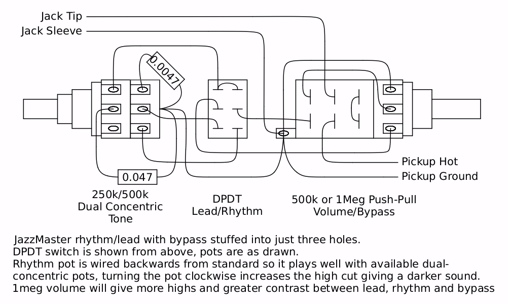
Was tasked with getting the most out of a tiny control panel and just one pickup so I crammed the JM circuit in and added a bypass. Good circuit for those that like the simplicity of a single pickup but want to eat their cake as well. Adding a second switch or rewiring the bypass would be a simple matter for two pickup guitars. Good circuit for the telecaster and its decedents, a single pickup telemaster with this circuit would be good fun.
Image
Logic gates based on billiard-ball computer designs have also been made to operate using live soldier crabs of the species Mictyris guinotae in place of the billiard balls.

User avatar
oid
PAT. # 2.972.923
PAT. # 2.972.923
Posts: 834
Joined: Sat Feb 10, 2018 8:19 pm

Re: Shadoweclipse13's Master Schematic Page!

Post by oid » Sun Oct 27, 2019 10:02 pm

epizootics wrote:
Sun Oct 27, 2019 9:49 pm
I'll be making those pickups (that's s'posed to be one of my activities :) )
I pop in from time to time but generally only talk when someone pokes me. Having the single coil in series with the like half of the hb might be what you are trying for, it is not a split coil since the other half of the humbucker is still on, it would be closer to all three pickups of a strat on at the same time. So more output, likely a bit more of the single coil sound and a decent amount of humbucking.
Logic gates based on billiard-ball computer designs have also been made to operate using live soldier crabs of the species Mictyris guinotae in place of the billiard balls.

User avatar
epizootics
PAT. # 2.972.923
PAT. # 2.972.923
Posts: 719
Joined: Wed Jun 28, 2017 10:29 pm
Location: Lyon, France

Re: Shadoweclipse13's Master Schematic Page!

Post by epizootics » Sun Oct 27, 2019 10:10 pm

oid wrote:
Sun Oct 27, 2019 10:02 pm
epizootics wrote:
Sun Oct 27, 2019 9:49 pm
I'll be making those pickups (that's s'posed to be one of my activities :) )
I pop in from time to time but generally only talk when someone pokes me. Having the single coil in series with the like half of the hb might be what you are trying for, it is not a split coil since the other half of the humbucker is still on, it would be closer to all three pickups of a strat on at the same time. So more output, likely a bit more of the single coil sound and a decent amount of humbucking.
Dang! I read your post too quick. This is actually another good option.
Your interventions are missed, it's always nice to have you chiming in :)

User avatar
Shadoweclipse13
PAT. # 2.972.923
PAT. # 2.972.923
Posts: 12446
Joined: Fri Feb 07, 2014 9:22 pm
Location: Stuck in the dimension of imagination

Re: Shadoweclipse13's Master Schematic Page!

Post by Shadoweclipse13 » Sun Oct 27, 2019 10:19 pm

epizootics wrote:
Sun Oct 27, 2019 10:10 pm
Dang! I read your post too quick. This is actually another good option.
Your interventions are missed, it's always nice to have you chiming in :)
Seconded!
Pickup Switching Mad Scientist
http://www.offsetguitars.com/forums/viewtopic.php?f=8&t=104282&p=1438384#p1438384

Post Reply