Need Feedback on experimental Wiring Diagram

Talk about modding or building your own guitar from scratch.
Post Reply
User avatar
JohnSimonson
PAT PEND
PAT PEND
Posts: 15
Joined: Tue Jan 15, 2019 5:17 am

Need Feedback on experimental Wiring Diagram

Post by JohnSimonson » Wed Feb 27, 2019 12:24 pm

Hi there,

I'm super new here and was hoping, that some of you might be able to help me out.

I'm currently working on my first project building my own offset design (I'll post a separate thread on that soon) and I came up with a pretty insane switching system.
I already revised it twice and had to remove one switch because I couldn't find a way to make it work.

The basic setup is as follows (and refers to the attached diagram I made in DIYLC):
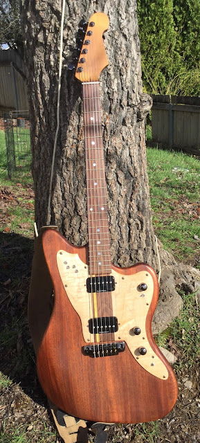
The guitar will have three Jaguar Style single coils. One in the Neck position and two in the Bridge position functioning as a kind of humbucker.

1. Each coil is first wired to a phase-switch (3 phase-switches total on the right next to the PUs)

2. The two bridge coils are then wired to a series-parallel-switch followed by a threeway coilselector switch (pawn shop mustang style).

3. Now it gets experimental. In addition to a Master Volume (topmost pot, comes later in the circuit) I have a Volume and Tone with a threeway assignment-switch each. The thought is, that I can switch those pots to work either on the two bridge PUs, the one Neck PU or all three when in the middle position.
I've never seen this done anywhere so I came up with my own solution as you can see in the diagram.

MAIN QUESTION: would this kind of mustang style switch wired in that fashion actually give me the desired effect, without mixing Brigde and Neck signal or shorting out or something? I really need your help here.

4. After the assignable Volume and Tone comes a standard threeway toggle like in a Jazzmaster. There you can select Neck, both or Bridge 'humbucker'

5. Lastly the previously mentioned Master Volume and then straight to the output.

What do you all think? Would this work? I currently don't have the means to test it and would be really grateful for any of your feedback.

Thanks!
John

Image

User avatar
Futuron
PAT. # 2.972.923
PAT. # 2.972.923
Posts: 1228
Joined: Fri Nov 10, 2017 3:19 am
Location: Australia

Re: Need Feedback on experimental Wiring Diagram

Post by Futuron » Wed Feb 27, 2019 5:51 pm

1. looks good

2. I don't know what you're hoping for, but what you've got is
IN SERIES: middle, series, bridge
IN PARALLEL: parallel, parallel, parallel

3. I believe that you've shorted the pickups together when either DP3T slider is in the middle position, meaning your 3-way toggle switch becomes irrelevant in those cases. If you were to instead use dual-gang pots (where a single shaft controls 2 separate signals at once, like a stereo volume knob) then you could possibly get the result you want. In that case the neck would be sent to one set of terminals, and the humbucker to the other set. So the top left terminal of the slider is to the neck pickup, the 2nd & 3rd left are to the 1st layer of the volume pot, the bottom left is empty. The bottom right terminal is the humbucker pickup, the 2nd & 3rd right are the 2nd layer of the volume pot, the top right is empty. Repeat for the tone pot.

Image

Also I think your optional volume pot is shorted to ground, making that slider effectively a kill switch. You should have wired the middle terminal and one of the others, not both end terminals, I believe.

User avatar
JohnSimonson
PAT PEND
PAT PEND
Posts: 15
Joined: Tue Jan 15, 2019 5:17 am

Re: Need Feedback on experimental Wiring Diagram

Post by JohnSimonson » Thu Feb 28, 2019 12:45 am

Thanks for the quick reply.

1. Great

2. That's not entirely what I'm after. I was hoping for
IN SERIES: middle, series, bridge
IN PARALLEL: middle, parallel, bridge
Any ideas, how that might be achieved?

3. dual-gang pots sound really interesting, I'll have to look into that! Thank you!

And I'll also have a look at the volume pot...

User avatar
Futuron
PAT. # 2.972.923
PAT. # 2.972.923
Posts: 1228
Joined: Fri Nov 10, 2017 3:19 am
Location: Australia

Re: Need Feedback on experimental Wiring Diagram

Post by Futuron » Sun Mar 03, 2019 6:11 pm

JohnSimonson wrote:
Thu Feb 28, 2019 12:45 am
2. That's not entirely what I'm after. I was hoping for
IN SERIES: middle, series, bridge
IN PARALLEL: middle, parallel, bridge
Any ideas, how that might be achieved?
Using those particular switches, I couldn't come up with a way to have exactly those 6 settings. The best I could find was 4 or 5, due to the simplicity of the switches and amount of connections required. If the DP3T (your 3-way coil selector) was a 3P3T I believe you would be set (3 columns of contacts instead of 2, but still only 3 switch settings).

Image

User avatar
JohnSimonson
PAT PEND
PAT PEND
Posts: 15
Joined: Tue Jan 15, 2019 5:17 am

Re: Need Feedback on experimental Wiring Diagram

Post by JohnSimonson » Thu Mar 14, 2019 4:14 am

Wow I didn't even know those existed. That's really cool, thank you!

User avatar
hpr_hpr
PAT. # 2.972.923
PAT. # 2.972.923
Posts: 434
Joined: Fri Apr 03, 2015 9:48 am

Re: Need Feedback on experimental Wiring Diagram

Post by hpr_hpr » Sun Mar 17, 2019 8:02 pm

One other note ..
If the bridge pickups are as close as you describe you will never use (other than in an experimental setting to verify the next statement) these two out of phase as they will almost completely cancel each other out ... the out of phase sound will be a very high pitched thin low intensity sound. You really only need the phase switch on the neck pickup.

Also the standard wiring for a volume pot is to use it as a voltage divider (see the master volume in the diagram). The problem you have is that in the current configuration you can't wire the optional volume that way ... so you have to wire it as a current divider (which would require wiring the center terminal on that pot to ground as well) which isn't quite what you want. Using two concentric pots for the optional volume & and tone (one for neck & one for bridge) would make it possible to use the standard wiring AND get rid of a bunch of switches making your control layout easier to manage.

Finally before you order the 3p3t slider switches make sure of their dimensions ... I have some but they are full size and thus about 3 fold larger than the standard mini switch size commonly used in guitars. I haven't yet found them as mini switches, if you do please let me know who makes and/or sells them.
When thinking about any advice given always ask yourself "why would (s)he know more than I do".

User avatar
JohnSimonson
PAT PEND
PAT PEND
Posts: 15
Joined: Tue Jan 15, 2019 5:17 am

Re: Need Feedback on experimental Wiring Diagram

Post by JohnSimonson » Sat Apr 06, 2019 5:17 pm

Hi Guys,
first of all, thanks for all your feedback, it really helped. The dual gang pots might just be a life saver, as they give me the possibility of having a set of soldering lugs for each pickup.

I did a lot of digging online for those pots and also the three row slide switches with no real luck (shipping to Germany was about five times the price of the actual parts). In the end I found the pots on amazon but had no luck with the switches.

I'm not one to give up easily so I just spent several hours trying to find a way to get my series/parallel switch to work with the coil selector and I think I found a surprisingly simple solution (see attached diagram v02).

Also I kept the phase switches for all three pickups. I know, I won't need them, but I just like having lots of switches like on the old european and japanese guitars of the 60s and who knows, maybe they'll yield some interesting sounds.

I know, those switches are huge and bulky, but they look so much cooler than mini toggles. I'll make room for them.

Really looking forward to your thoughts on the new schematic (I had to improvise a bit to make dual gang pots work in DIYLC)

Image

User avatar
JohnSimonson
PAT PEND
PAT PEND
Posts: 15
Joined: Tue Jan 15, 2019 5:17 am

Re: Need Feedback on experimental Wiring Diagram

Post by JohnSimonson » Sun Apr 07, 2019 2:32 am

@hpr_hpr just noticed I haven't even adressed the voltage divider vs. current divider issue.

How would this affect my signal/tone? I know, having concentric pots would make it a lot cleaner, but I really want the switch and a single knob...

I'll look into a solution, there has to be a way to get normal volume pot wiring out of a switch and the dual gang pot.

User avatar
JohnSimonson
PAT PEND
PAT PEND
Posts: 15
Joined: Tue Jan 15, 2019 5:17 am

Re: Need Feedback on experimental Wiring Diagram

Post by JohnSimonson » Sun Apr 07, 2019 3:01 am

Right, here's what I came up with for the assignable volume pot. I'm not sure whether I might loose signal when the switch is in "bypass" mode, or there might be some grounding issues.

I'm really out of my depth here, considering my very basic understanding of electronics, so any feedback is welcome.

Image

User avatar
JohnSimonson
PAT PEND
PAT PEND
Posts: 15
Joined: Tue Jan 15, 2019 5:17 am

Re: Need Feedback on experimental Wiring Diagram

Post by JohnSimonson » Mon Apr 22, 2019 12:51 pm

Alright, I think I might have reached the final stages of refining the wiring. Below is the current diagram which I am pretty sure might actually work.
I implemented the volume pot fix I posted before and also fixed the whole series parallel + coil selector fiasco (at least I think I fixed it).

It would be great to get one last round of feedback if you have the endurance to actually try and get through this very convoluted mess of switches, wires and pots.

Im really looking forward to what you have to say. I'll probably go ahead and try this setup on the actual project, as soon as it's ready.

Thanks

Image

User avatar
timtam
PAT. # 2.972.923
PAT. # 2.972.923
Posts: 2739
Joined: Sun Oct 22, 2017 2:42 am
Location: Melbourne

Re: Need Feedback on experimental Wiring Diagram

Post by timtam » Mon Apr 22, 2019 5:38 pm

That is a complex diagram ! I think your choices now for determining if it will work are ...
1. Wire it up and see. ;)
2. Convert it from a wiring diagram to a schematic. That's usually where complex new wiring schemes should actually start ... with the wiring diagram following only once the schematic has all the desired functionality (and none undesired). Once you've done one you'll realize that they are actually much simpler to follow than a wiring diagram. And they show errors much more clearly.
3. A 'halfway' option to 2 ... print out as many copies of your wiring diagram as there are switch position combinations. For each printout / switch position combination, overdraw the switch-selected signal paths with a highlighter. That should show if you have all the functionality that you want, and none that you don't. Start with a list of all possible switch position combinations to determine how many printouts you need. You could omit printouts for the phase switches - their function is clear.
"I just knew I wanted to make a sound that was the complete opposite of a Les Paul, and that’s pretty much a Jaguar." Rowland S. Howard.

User avatar
hpr_hpr
PAT. # 2.972.923
PAT. # 2.972.923
Posts: 434
Joined: Fri Apr 03, 2015 9:48 am

Re: Need Feedback on experimental Wiring Diagram

Post by hpr_hpr » Fri Apr 26, 2019 1:47 pm

Ok,
1. this is one of the more complex diagrams I have seen . . . and if it's your first time doing something like this I have to warn you that you might have bitten off more than you can chew. I have something equally complex in my modified JM with all the options on a pair of SD pRails pickups (6 DPDT, 1 DPTT, 1 SPDT, 1 3P4T Rotary switch, Vol & Tone) and it took me 2 whole days of solid work to put it all together . . . . while it IS tempting to have ALL the options available (especially with pRails, it's why I have them on that JM) I have since found that at least with regular pickups you really only use a small subset . . . even with the pRails (combination of a P90 and a single coil rail in a humbucker) I find that there are quite a few configurations that are tonally quite similar.
2. The just wire it up and see if it works . . . is fine . . . if it works, the more complex the wiring the bigger the nightmare chasing down any faults . . . you do have a multimeter right . . .
3. I will reiterate the 'please cut the phase switches on the bridge', they are a complication you don't need . . . you'll never use them to put the 2 coils at the bridge out of phase as it will kill your volume (and result in a very high pitched tone to boot), you only will only need/use the phase switch on the neck pickup in real life.
3a. there IS a reason to have a series/parallel switch on the 2 bridge coils. However, it's unlikely that selecting either coil single (with them being as close as they are) will result in a noticebly different tone unless the coils themselves are substancially different (in which case there MAY be a reason for the phase switches as well but it's still a bit far fetched)

SO . . . especially if this is your first go at soldering . . . and every solder joint is potential trouble point . . . simplify . . . it will also allow you to get this done that much faster (and you can always modify things to a more complex form later as well) and avoid the "if I just get this done I will be finished" syndrome that will result in mistakes and bad soldering.

Finally you are missing the earth on the jack . . . and the signal should go to the tip . . . not sure if that's drawn right as I don't have an example in front of me.
When thinking about any advice given always ask yourself "why would (s)he know more than I do".

User avatar
JohnSimonson
PAT PEND
PAT PEND
Posts: 15
Joined: Tue Jan 15, 2019 5:17 am

Re: Need Feedback on experimental Wiring Diagram

Post by JohnSimonson » Mon Apr 29, 2019 7:05 am

Wow, this is a lot of feedback, thanks so much you two.

First of all, while it is my first time doing this, I'll have a friend help me wire it up who is both a guitarist and an electrician and has soldered lots of pedals and guitars before. He also has a multimeter and a high quality soldering iron.

I already went through all the switching combinations multiple times, following the signal flow and as far as I can see, this last iteration should be pretty much flawless (if there is such a thing).

I know I won't need all these options and I know the phase switches on the bridge pickups are a bit overkill but I just love those vintage japanese and european guitars just littered with switches and that's kind of what I'm going for, while trying to give each of them an actual purpose. I know it's all a bit stupid and pointless but hey, as long as it's fun, right? Plus I just think the assignable volume and tone pots are a good idea in general.

The two bridgepickups are similar but do have very different output levels. That would make it interesting to have one cleaner/quieter bridge sound and a more agressive/dirtier bridge sound as well as both of them together just through the flick of a switch.

I guess my best bet is to actually wire it up and see. If there's no obvious flaws that jump out to you (except the wiring of the output jack which is just due to lazyness) I'm already pretty comfortable moving forward.

All in all, thanks so much for your help. I'll start a separate thread covering the build in general and post a link here if you're interested in the end result.

@hpr_hpr that p-rail Jazzmaster of yours sounds awesome! Do you have a thread about that?

User avatar
hpr_hpr
PAT. # 2.972.923
PAT. # 2.972.923
Posts: 434
Joined: Fri Apr 03, 2015 9:48 am

Re: Need Feedback on experimental Wiring Diagram

Post by hpr_hpr » Mon Apr 29, 2019 2:37 pm

Ah, that helps . . . it's still going to be A LOT of work though.

As to the JM, here is a picture, it has since acquired one more switch in the area where a normal JM's jack is (the jack is on the side). The switches in the upper bout switch the pickup coils (rail, series, parallel, P90), the 4 way rotary pickup selector (neck, series, parallel, bridge) is in the lower bout with a phase switch and the switch in the back here switches the tone circuit pre-volume/off/post-volume. The extra switch not on here is an on/off for a treble bleed. The next revision will be to eliminate the pre/off/pos volume on the tone and have it switch between 2 different caps I think as that may be more useful.
Image

and here is the diagram to go with it.
https://buildsomethinganything.blogspot ... iring.html
When thinking about any advice given always ask yourself "why would (s)he know more than I do".

User avatar
JohnSimonson
PAT PEND
PAT PEND
Posts: 15
Joined: Tue Jan 15, 2019 5:17 am

Re: Need Feedback on experimental Wiring Diagram

Post by JohnSimonson » Fri Apr 03, 2020 12:08 pm

Hey Guys,

I know it's been ages, but the guitar is finally finished and after a couple more adjustments a friend of mine and I got the wiring to work and it's awesome!

Thanks so much for your help! I am truly grateful.

If you want to read about the build process and see some pictures, here's a really long post I just made about it http://www.offsetguitars.com/forums/vie ... 3#p1608443

Post Reply