Hello!
I'm looking to do some mods for my J Mascis Jazzmaster. Specifically I'm looking to mod the wiring. What I'd like to do is remove the tone pot from the lead circuit and make the up position of the 2 way switch put the pickups in series. I don't plan on using the tone on the "rhythm" side either. So I know I would need to use 500k pots for the volume. I don't know how to modify the wiring in order to attain the desired result without also screwing up the tone (eg. what caps/resistors should I use and where). Does anyone else know how this would be done? Keep in mind I am confident with my soldering but have basic wiring knowledge.
Thanks!
Wiring mod for my J. Mascis
-
Shadoweclipse13

- PAT. # 2.972.923

- Posts: 12446
- Joined: Fri Feb 07, 2014 9:22 pm
- Location: Stuck in the dimension of imagination
Re: Wiring mod for my J. Mascis
So you're just looking for 2 volumes, no tones, and series wiring?
Pickup Switching Mad Scientist
http://www.offsetguitars.com/forums/viewtopic.php?f=8&t=104282&p=1438384#p1438384
http://www.offsetguitars.com/forums/viewtopic.php?f=8&t=104282&p=1438384#p1438384
-
hpr_hpr

- PAT. # 2.972.923
- Posts: 434
- Joined: Fri Apr 03, 2015 9:48 am
Re: Wiring mod for my J. Mascis
OK, one thing of note is that HOWEVER you change the wiring it WILL change the tone, changing any electrical circuit will change it properties . . . the question is wether a human can hear that change.
OK so what you want to en up with according to your description is this:
original pickup switch = neck / parallel bridge
rhythm circuit switch = series / original pickup switch
one volume each for bridge and neck
master tone
Is that correct? This should get you started . . .
OK so what you want to en up with according to your description is this:
original pickup switch = neck / parallel bridge
rhythm circuit switch = series / original pickup switch
one volume each for bridge and neck
master tone
Is that correct? This should get you started . . .
Last edited by hpr_hpr on Tue Jan 16, 2018 12:43 pm, edited 2 times in total.
When thinking about any advice given always ask yourself "why would (s)he know more than I do".
-
Spook100

- PAT PEND

- Posts: 12
- Joined: Mon Jan 15, 2018 8:21 pm
Re: Wiring mod for my J. Mascis
I'm looking for a volume in the lead circuit and a volume in the rhythm circuit. I want the rhythm circuit to be both pickups in series and the lead circuit to be the normal neck/both/bridge on the 3 way switch.
I know that any change to the wiring will affect the tone. I guess what I meant was I want to be sure that what I take out of the circuit is replaced via caps and resistors so I don't screw up the tone. I'm not sure if that makes sense. I prefer a warmer less trebly sound so whatever I change it to I'm looking for it to lean towards the warmer side of things.
I know that any change to the wiring will affect the tone. I guess what I meant was I want to be sure that what I take out of the circuit is replaced via caps and resistors so I don't screw up the tone. I'm not sure if that makes sense. I prefer a warmer less trebly sound so whatever I change it to I'm looking for it to lean towards the warmer side of things.
-
hpr_hpr
- PAT. # 2.972.923
- Posts: 434
- Joined: Fri Apr 03, 2015 9:48 am
Re: Wiring mod for my J. Mascis
The rhythm circuit is completely disconnected with the rhythm switch 'off' so anything electrical there is just sitting there not doing anything so the values are moot when using 'regular' settings (the opposite also is true, when the rhythm circuit is 'on' the regular tone & volume are out of the circuit) .
Volumes should probably be 1M pots as in the original . . . keep any treble bleed on the volume and put the same bleed on the other volume for the closest tone . . . if you want less treble remove any bleeds. If you delete the tone pot you will get bit 'brighter sound' as there will be NO bleed as opposed to with the pots max resistance bleed (with isn't much at 1M but still some) . . . if you want a warmer tone I would install at least a master tone in one of the rhythm locations . . . 250K and 0.33uf would be a starting value, smaller resistance attenuates more treble and larger caps (say 0.47 uf) attenuate more treble for the same resistance value . . .
DIGRESSION #1:
it's actually more complicated than that ; larger caps have a lower frequency cutoff . . . which also depends on the current resistance set on the volume pot - which is why changing the volume changes the tone - thus treble bleed circuits - . . . and the impedance of the pickups plays a role . . . and ... well electrical circuit behavior becomes complicated when mixing all these resistors, coils and capacitors
but that's what your ears will tell you . . . you can also keep the 1meg pot there as the ACTUAL (set) resistance is more important than the MAX resistance of that pot - tone pots themselves actually pretty much only influence the tone with their actual - set - resistance value, the max value only comes into play when you want minimal effect on the tone.
DIGRESSION #2:
This is there reason for the lower pot values for single coils; it removes the 'harshness' even when the tone pots are at max resistance, hum buckers are 'warmer' in and off themselves and thus can have larger max values (less treble attenuation).
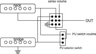
I think this would be the closest you can come with the current switches .... (note that crossed wires do NOT connect in this schematic). . .
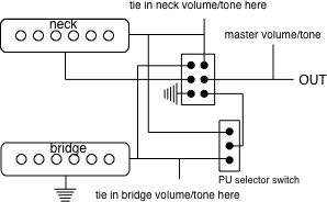
if you want a completely SEPARATE volume for both situations you would need to replace the 'rhythm switch' with a 3PDT switch . . . you need the extra pole to switch out the volume on the series circuit . . . I think . . . .
Shadoweclipse13's Master Schematic Page! in this section may have an alternative/better solution as well . . .
Volumes should probably be 1M pots as in the original . . . keep any treble bleed on the volume and put the same bleed on the other volume for the closest tone . . . if you want less treble remove any bleeds. If you delete the tone pot you will get bit 'brighter sound' as there will be NO bleed as opposed to with the pots max resistance bleed (with isn't much at 1M but still some) . . . if you want a warmer tone I would install at least a master tone in one of the rhythm locations . . . 250K and 0.33uf would be a starting value, smaller resistance attenuates more treble and larger caps (say 0.47 uf) attenuate more treble for the same resistance value . . .
DIGRESSION #1:
it's actually more complicated than that ;
but that's what your ears will tell you . . . you can also keep the 1meg pot there as the ACTUAL (set) resistance is more important than the MAX resistance of that pot - tone pots themselves actually pretty much only influence the tone with their actual - set - resistance value, the max value only comes into play when you want minimal effect on the tone.
DIGRESSION #2:
This is there reason for the lower pot values for single coils; it removes the 'harshness' even when the tone pots are at max resistance, hum buckers are 'warmer' in and off themselves and thus can have larger max values (less treble attenuation).
I think this would be the closest you can come with the current switches .... (note that crossed wires do NOT connect in this schematic). . .
if you want a completely SEPARATE volume for both situations you would need to replace the 'rhythm switch' with a 3PDT switch . . . you need the extra pole to switch out the volume on the series circuit . . . I think . . . .
Shadoweclipse13's Master Schematic Page! in this section may have an alternative/better solution as well . . .
When thinking about any advice given always ask yourself "why would (s)he know more than I do".
-
Shadoweclipse13
- PAT. # 2.972.923
- Posts: 12446
- Joined: Fri Feb 07, 2014 9:22 pm
- Location: Stuck in the dimension of imagination
Re: Wiring mod for my J. Mascis
It might, but if not, let me know. I can draw something up for you pretty quickly...
Pickup Switching Mad Scientist
http://www.offsetguitars.com/forums/viewtopic.php?f=8&t=104282&p=1438384#p1438384
http://www.offsetguitars.com/forums/viewtopic.php?f=8&t=104282&p=1438384#p1438384
-
Spook100
- PAT PEND
- Posts: 12
- Joined: Mon Jan 15, 2018 8:21 pm
Re: Wiring mod for my J. Mascis
Hmmm... this project may be outside my abilities. I've done simply stuff like swapping parts like-for-like but this seems pretty complicated.
I'd be cool with just a single master volume and tone for the whole thing on the roller knobs as I'd like to plug the holes where the standard knobs are. However I'm a newb when it comes to wiring so I might be aiming too high for my skill level.
I'd be cool with just a single master volume and tone for the whole thing on the roller knobs as I'd like to plug the holes where the standard knobs are. However I'm a newb when it comes to wiring so I might be aiming too high for my skill level.
-
Shadoweclipse13
- PAT. # 2.972.923
- Posts: 12446
- Joined: Fri Feb 07, 2014 9:22 pm
- Location: Stuck in the dimension of imagination
Re: Wiring mod for my J. Mascis
This one is actually pretty simple. If you can follow a schematic and solder reasonably well, this one wouldn't be too bad.Spook100 wrote: ↑Tue Jan 16, 2018 4:18 pmHmmm... this project may be outside my abilities. I've done simply stuff like swapping parts like-for-like but this seems pretty complicated.
I'd be cool with just a single master volume and tone for the whole thing on the roller knobs as I'd like to plug the holes where the standard knobs are. However I'm a newb when it comes to wiring so I might be aiming too high for my skill level.
Pickup Switching Mad Scientist
http://www.offsetguitars.com/forums/viewtopic.php?f=8&t=104282&p=1438384#p1438384
http://www.offsetguitars.com/forums/viewtopic.php?f=8&t=104282&p=1438384#p1438384
-
Spook100
- PAT PEND
- Posts: 12
- Joined: Mon Jan 15, 2018 8:21 pm
Re: Wiring mod for my J. Mascis
I mostly understand the schematics hpr posted but not enough to start pulling wires. I would need a more detailed/complete diagram showing what wires went to each component if I was gonna attempt it one my own. If you know of something like that out there I'd be set.
-
Shadoweclipse13
- PAT. # 2.972.923
- Posts: 12446
- Joined: Fri Feb 07, 2014 9:22 pm
- Location: Stuck in the dimension of imagination
Re: Wiring mod for my J. Mascis
That's what I doSpook100 wrote: ↑Tue Jan 16, 2018 6:12 pmI mostly understand the schematics hpr posted but not enough to start pulling wires. I would need a more detailed/complete diagram showing what wires went to each component if I was gonna attempt it one my own. If you know of something like that out there I'd be set.
Pickup Switching Mad Scientist
http://www.offsetguitars.com/forums/viewtopic.php?f=8&t=104282&p=1438384#p1438384
http://www.offsetguitars.com/forums/viewtopic.php?f=8&t=104282&p=1438384#p1438384
-
Spook100
- PAT PEND
- Posts: 12
- Joined: Mon Jan 15, 2018 8:21 pm
Re: Wiring mod for my J. Mascis
Holy Cow! Really? Thanks man! I'm new here so I was unaware of your awesomeness.
Lemme try and articulate this properly since my idea as to what I want has shifted a bit in this conversation.
I'd like to make the rollers be the master volume and tone that control both the lead and rhythm circuits and completely remove the lower volume and tone pots.
I'd like the rhythm circuit (when the 2 way switch is up) to switch both pickups on in series (ala humbucker).
I'd like the lead circuit(when the 2 way switch is down) with the 3 way switch to behave like it normally does with the option being Neck Only/Neck+Bridge(parallel?)/Bridge Only
I was thinking about going with a 500k volume pot to remove a bit more treble but if changing the caps would be a better option I'm ok with that as well.
Thanks for all your help.
-
hpr_hpr
- PAT. # 2.972.923
- Posts: 434
- Joined: Fri Apr 03, 2015 9:48 am
Re: Wiring mod for my J. Mascis
We're here to help . . . . 
When thinking about any advice given always ask yourself "why would (s)he know more than I do".
-
SY6655321
- PAT. # 2.972.923
- Posts: 136
- Joined: Sun Mar 17, 2013 8:12 pm

-
Spook100
- PAT PEND
- Posts: 12
- Joined: Mon Jan 15, 2018 8:21 pm
Re: Wiring mod for my J. Mascis
Awesome!
Just so I fully understand I have a few questions.
Based on this schematic there is only 1 capacitor?
Will there be anything soldered to the back of either pot?
Where it indicates "to ground" would those be soldered to the guitar cavity (which will be completely copper lined)?
Sorry if these are lame questions
-
hpr_hpr
- PAT. # 2.972.923
- Posts: 434
- Joined: Fri Apr 03, 2015 9:48 am
Re: Wiring mod for my J. Mascis
Yes, for the tone pot
The pot casings should be grounded as should the pickups if they have a separate (from the signal) ground wire (that would be more than 2 wires for single coil Pus, and more than 4 for hum bucker style)
Solder grounds to the shielding on the pick guard (I'm assuming that if you are lining the cavities you are also lining the back for the guard if it isn't already) then when lining the cavity have the shielding come up around at least one of the pick guard screws and extend the guard shielding to cover that screw hole as well then when you screw down the guard it will complete the electrical connection there.
And no, there are no lame (or stupid) questions if you're unsure . . . ASK . . . it saves you a lot of grief if your assumptions prove to be wrong and may prevent you from doing something that isn't (easily) reversible.
When thinking about any advice given always ask yourself "why would (s)he know more than I do".