Wiring mod for my J. Mascis
-
Shadoweclipse13

- PAT. # 2.972.923

- Posts: 12446
- Joined: Fri Feb 07, 2014 9:22 pm
- Location: Stuck in the dimension of imagination
Re: Wiring mod for my J. Mascis
Damn! Beat me to it! Haha. That will be a very cool Jazzmaster!!
Pickup Switching Mad Scientist
http://www.offsetguitars.com/forums/viewtopic.php?f=8&t=104282&p=1438384#p1438384
http://www.offsetguitars.com/forums/viewtopic.php?f=8&t=104282&p=1438384#p1438384
-
hpr_hpr

- PAT. # 2.972.923
- Posts: 434
- Joined: Fri Apr 03, 2015 9:48 am
Re: Wiring mod for my J. Mascis
Oh and one more thing . . . when using multiple pieces of copper lining, no matter WHAT the manufacturer claims, ALWAYS make a solder connection between adjacent pieces somewhere unless you can positively verify that you have electrical continuity . . . I've found that even with the manufacturer claiming 'electrical conductive adhesive' it doesn't always actually 'work as advertised' and those are pesky problems to chase down unless you have a multimeter, or continuity detector (2 wires a battery and a low voltage bulb), handy . . .
When thinking about any advice given always ask yourself "why would (s)he know more than I do".
-
Spook100

- PAT PEND

- Posts: 12
- Joined: Mon Jan 15, 2018 8:21 pm
Re: Wiring mod for my J. Mascis
Ok cool, I have a multimeter I can check it with. I'll probably use solder anyways to verify I have good continuity throughout.
I have another couple of quick questions. Are the pot used for the roller knobs mini pots? I wanna replace the crappy ones that are in there as long as I'm swapping stuff around. If they are mini ones can anyone point me to a good source to get them from?
Also if I wanted to experiment with throwing a Greasebucket circuit on there where would that go?
Thanks again for all your help so far. I'll keep this updated as I proceed with the project.
-
hpr_hpr
- PAT. # 2.972.923
- Posts: 434
- Joined: Fri Apr 03, 2015 9:48 am
Re: Wiring mod for my J. Mascis
Yes the roller pots are mini's ... I just ordered a pair for a different project HERE https://www.amazon.com/gp/product/B01H7 ... UTF8&psc=1 Bourns is a reputable manufacturer. These are 250K audio taper. The problem is finding them with the right shaft diameter . . . depending on were your guitar was built the ID of the roller knobs may be 1/4" - easy(er) to find - or 6 mm - hard here in the US. Aside from Bourns, CTS has a good reputation (but I think they don't do metric) and I've got good luck with Alpha (Taiwan) as well. The 'traditional sources' for electronics gear are mouser and digikey . . . they literally can get you ANYTHING - though sometimes only in lots of 100 or more  )
)
A grease bucket circuit
an example with the differences with a regular tone (4.7K resistor and 0.022 uf cap and interchanged in the circuit vs picture . . . not a big deal)
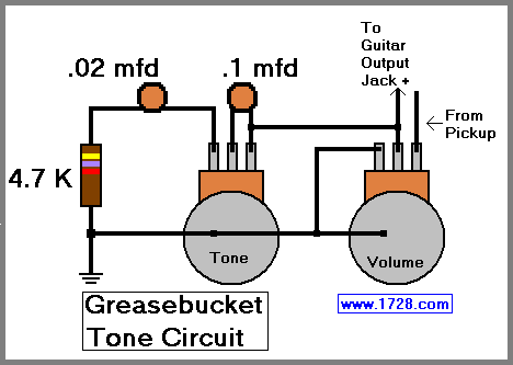
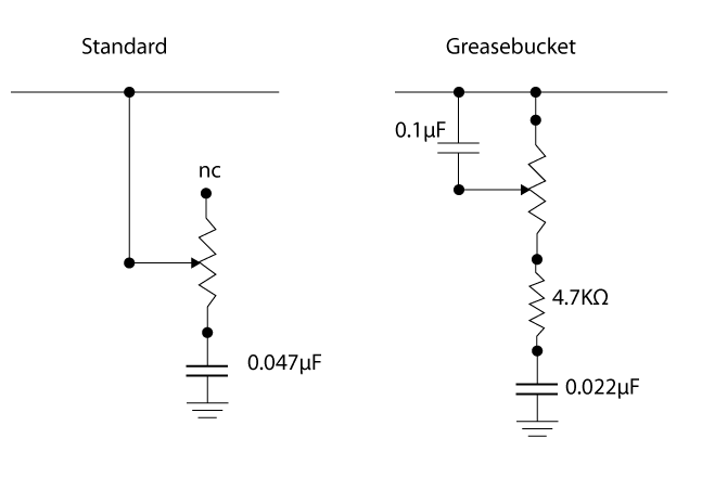
would necessitate another pot as you can see, were is connects to the wiper (middle lug) on the volume pot in the picture connect it to the tip of the output jack.
A grease bucket circuit
an example with the differences with a regular tone (4.7K resistor and 0.022 uf cap and interchanged in the circuit vs picture . . . not a big deal)
would necessitate another pot as you can see, were is connects to the wiper (middle lug) on the volume pot in the picture connect it to the tip of the output jack.
When thinking about any advice given always ask yourself "why would (s)he know more than I do".
-
Spook100
- PAT PEND
- Posts: 12
- Joined: Mon Jan 15, 2018 8:21 pm
Re: Wiring mod for my J. Mascis
OK, I've hit a speed bump.
Based on the schematic SY6655321 posted I need to route one lead of the bridge pickup to the 2 way switch and the other lead to the 3 way switch. Here's my problem (picture provided), I have one shielded lead coming from the pickup. I can see that the cloth wrapped center wire goes to one of the coil leads and the shielding is split to go to both the other coil lead and also grounded to the metal plate that sandwiches the magnets between it and the coil bobbin. How do I wire this up? Do I need to replace the shielded wire with two separate leads? If so do I split one to the metal plate as well?
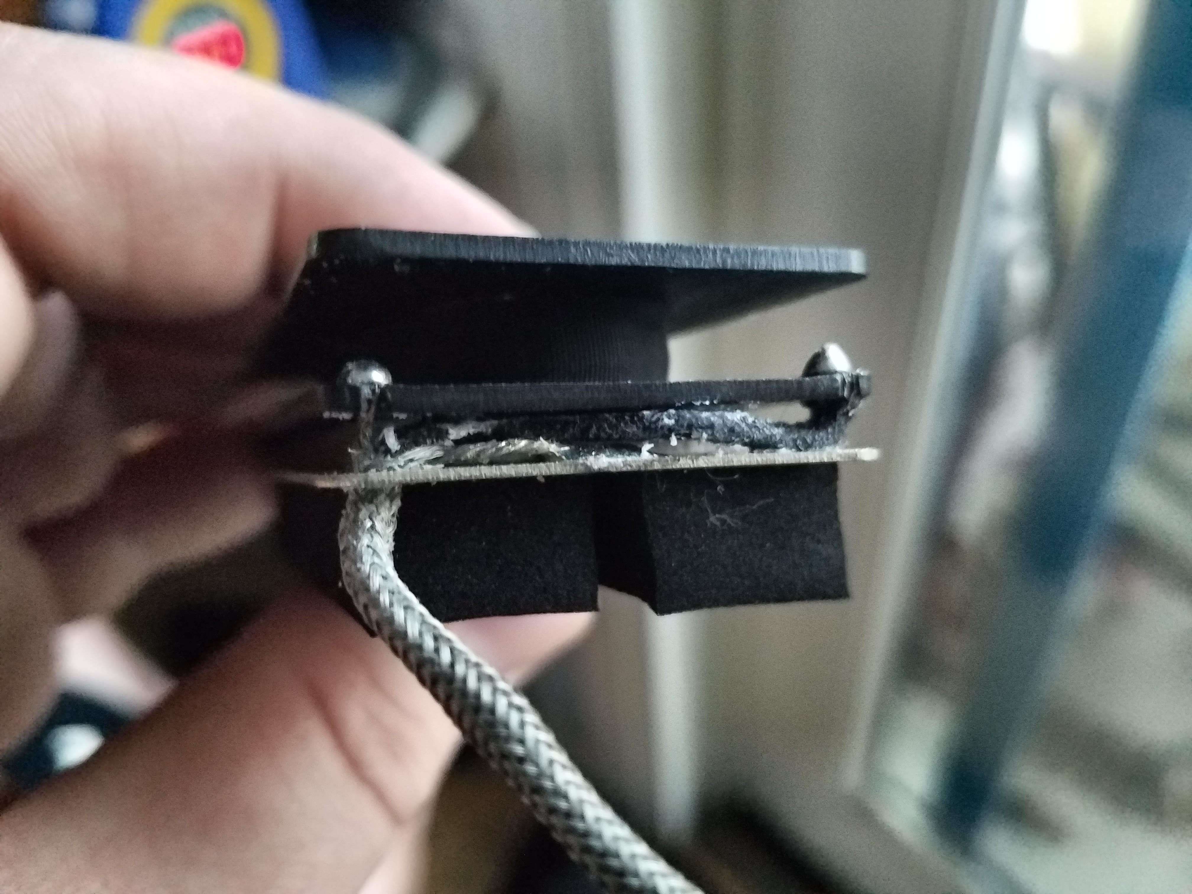
Thanks for the help!
Based on the schematic SY6655321 posted I need to route one lead of the bridge pickup to the 2 way switch and the other lead to the 3 way switch. Here's my problem (picture provided), I have one shielded lead coming from the pickup. I can see that the cloth wrapped center wire goes to one of the coil leads and the shielding is split to go to both the other coil lead and also grounded to the metal plate that sandwiches the magnets between it and the coil bobbin. How do I wire this up? Do I need to replace the shielded wire with two separate leads? If so do I split one to the metal plate as well?
Thanks for the help!
-
SY6655321
- PAT. # 2.972.923
- Posts: 136
- Joined: Sun Mar 17, 2013 8:12 pm
Re: Wiring mod for my J. Mascis
you can just use a seperate peice of wire from the 3-way switch to connect to the 2-way (the purple wire in the picture). Also added the greasebucket wiring to the diagram. I've got a greasebucket circuit in my jaguar and really like it. It sounds more natural to me than a normal tone control.

-
Spook100
- PAT PEND
- Posts: 12
- Joined: Mon Jan 15, 2018 8:21 pm
Re: Wiring mod for my J. Mascis
Awesome! I ordered the parts for both the original and this new one but I'm gonna try the original circuit you sent first and probably throw the grease bucket in later to compare it.
I'm still confused though with how to wire the bridge pickup.
1. Since I have only one shielded lead how do I wire it to each switch (since using the shield as a wire will ground it because it will be touching the shielding on the pickguard)?
OR
2. Should I replace the single shielded lead with 2 separate leads?
2a. If so, do I still need to solder one to the metal plate that sandwiches the magnets between it and the coil bobbin?
3. Does it matter which lead goes to which switch?
Sorry for so many questions.
-
hpr_hpr
- PAT. # 2.972.923
- Posts: 434
- Joined: Fri Apr 03, 2015 9:48 am
Re: Wiring mod for my J. Mascis
Shield is ground (for both casing.plate & coil), center is hot . . . . the easiest is to use it as if the shielding is ground for the coil and the center is hot, the plate/casing isn't actually grounded in all configurations that way but that shouldn't matter to much. I read the diagram as: hot goes to the 3 way switch, ground goes to to the rhythm switch . . . the alternative is to do surgery on the pickup and install separate leads for coil and casing/plate . . . be advised though that this is an expert level operation as you need to disassemble the pickup and can damage the coil lead(s) (extremely thin wire) and so render the PU inoperable. Bottom line on that, I would be hesitant to perform it myself on any pickup with more than minor value and not without trying it on a 'cheap' pickup first (although with all the permutations out there there is no guarantee that the wiring of any 2 pickups of different manufacture has such in common outside of the coils).
If you want to HAVE someone do it maybe your local shop will take it on OR try Sentell Pickups http://www.sentellpickups.net, his website says he repairs PUs so he will probably take this on as well . . . that said I have no experience with him beyond eying the (occasional) weird pickups on his site.
Q1, Q2, Q2a: see above
Q3: YES, wire it the 'wrong' way and the pickups will be out of phase . . . this usually means that you get a 'thin' or 'high' sound as the lower frequencies cancel out between the pickups . . . some of us find this useful and intentionally install a phase switch for one or more pickups so we can switch (the most famous example is probably Brian Mays red special which has phase switches on all three pickups)
When thinking about any advice given always ask yourself "why would (s)he know more than I do".
-
Spook100
- PAT PEND
- Posts: 12
- Joined: Mon Jan 15, 2018 8:21 pm
Re: Wiring mod for my J. Mascis
Should I encase the shield in heatshrink tubing so it doesn't ground out on the back of the pick guard?
-
hpr_hpr
- PAT. # 2.972.923
- Posts: 434
- Joined: Fri Apr 03, 2015 9:48 am
Re: Wiring mod for my J. Mascis
Good catch . . . yes that WOULD be a GOOD thing to do as it's now functioning as a signal carrier . . .
When thinking about any advice given always ask yourself "why would (s)he know more than I do".
-
Spook100
- PAT PEND
- Posts: 12
- Joined: Mon Jan 15, 2018 8:21 pm
Re: Wiring mod for my J. Mascis
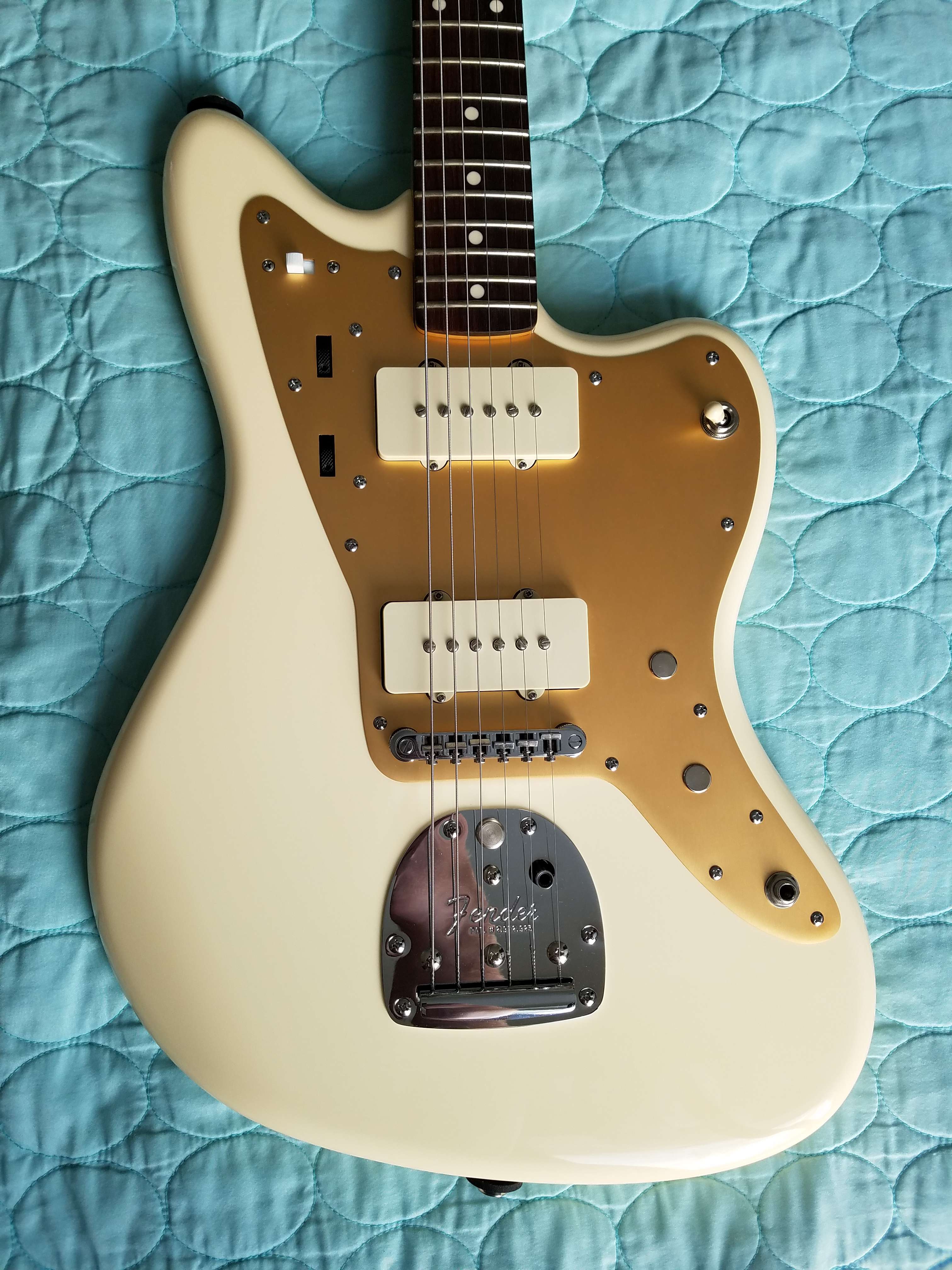
Ok, so I managed to get it all wired up and put together and it all seems to be working. First Try!
I've been playing it for a few hours now and I have 2 concerns.
1. The Up position on the 2 way switch seems kinda muddy. Not bad muddy more like a neck humbucker with the tone rolled off a bit. Is that to be expected?
2. The difference between the 2 pickups in series (2 way switch in the up position) and them in parallel (2 way switch in the down position and the 3 way switch in the middle position) in only very slight. In series they seem to have a tiny bit more growl but are a but muddy. In parallel they have a bit more top end with slightly less output. Is this to be expected?
Bonus picture of the guitar back together.
-
hpr_hpr
- PAT. # 2.972.923
- Posts: 434
- Joined: Fri Apr 03, 2015 9:48 am
Re: Wiring mod for my J. Mascis
Q1. OK UP put's them in series, down is the regular switch position right . . . . there may be a bit of phase cancellation of the high frequencies which would account for the 'muddier' tone, I've never wired a set of JM pickups in series so I can't speak to if it's to be expected.
Q2. Yes, the difference in tone between series and parallel is not all that great . . . there would be a much bigger difference as instead of putting the PUs in series you used that switch to phase switch one of the PUs . . . but then I don't know if you like the sound of JM pickups with the lower frequencies cancelled out . . . again, never tried that myself with JM PUs though I have a set of SD PRails and some cheap Tele hum-bucker rails that I can phase switch, the differences there are . . . noticeable . . . especially the PRails depending on the settings of the individual PUs.
Q2. Yes, the difference in tone between series and parallel is not all that great . . . there would be a much bigger difference as instead of putting the PUs in series you used that switch to phase switch one of the PUs . . . but then I don't know if you like the sound of JM pickups with the lower frequencies cancelled out . . . again, never tried that myself with JM PUs though I have a set of SD PRails and some cheap Tele hum-bucker rails that I can phase switch, the differences there are . . . noticeable . . . especially the PRails depending on the settings of the individual PUs.
When thinking about any advice given always ask yourself "why would (s)he know more than I do".
-
SY6655321
- PAT. # 2.972.923
- Posts: 136
- Joined: Sun Mar 17, 2013 8:12 pm
Re: Wiring mod for my J. Mascis
Nice job! What did you use to plug the lower volume and tone holes?
-
Spook100
- PAT PEND
- Posts: 12
- Joined: Mon Jan 15, 2018 8:21 pm
Re: Wiring mod for my J. Mascis
They are from Home Depot. They fit the holes almost perfectly.
https://www.homedepot.com/p/3-8-in-Meta ... /204273766
They pop right in but they spin in the hole. If you bend 2 of the prongs on the back they sit nice and tight.
https://www.homedepot.com/p/3-8-in-Meta ... /204273766
They pop right in but they spin in the hole. If you bend 2 of the prongs on the back they sit nice and tight.
-
MotorBongo

- PAT. # 2.972.923
- Posts: 80
- Joined: Wed Jun 05, 2013 2:40 am
- Location: EU
Re: Wiring mod for my J. Mascis
Hi,
Quick question for anyone with an 'opened' Sq JMJM at the bench (pickguard removed):
is the original pickguard doing all the shielding, or is there additional material (copper, or even aluminium ?!) attached on the inside of the pickguard ?
I don't recall this from when I had it opened.
Background to my question is that I'm considering adding an anodised alu pickguard for another JM, and might order&use an additional copper shield.
Or the same question in another way: did the 'old real Fender Jazzmasters' use the metal (alu/copper?) shield also when the pickguard was the aluminium anodised version ?
Thanks!
www.motorbongo.nl