Page 24 of 40
Re: Shadoweclipse13's Master Schematic Page!
Posted: Fri Feb 14, 2020 6:28 pm
by Futuron
It will use the north coil (green + white) and ignore the south (red + black). Don't forget to connect that bare wire to actual ground. And ground the switch casings too.
Re: Shadoweclipse13's Master Schematic Page!
Posted: Mon Feb 17, 2020 8:17 am
by Deadbe4r
Futuron wrote: ↑Fri Feb 14, 2020 6:28 pm
It will use the north coil (green + white) and ignore the south (red + black). Don't forget to connect that bare wire to actual ground. And ground the switch casings too.
Good deal. I appreciate your help. Here's revision 3, now in color!

Re: Shadoweclipse13's Master Schematic Page!
Posted: Sat Feb 22, 2020 3:46 pm
by JVG
Hey Shadow (and others good at wiring),
Can i configure a 3-way (mustang-style) slide switch to have a tone cap on either side?
Ideally i’d like the central position to be the unaffected signal, left position ‘bright’ cap, and right position ‘woman tone’ cap.
At first i thought this was simple, but then i got confused. I can see how it’s easy to have a tone cap on one side, but can i have them on both, while keeping the centre position normal?

Cheers!
J.
Re: Shadoweclipse13's Master Schematic Page!
Posted: Sun Feb 23, 2020 2:34 am
by Futuron
JVG wrote: ↑Sat Feb 22, 2020 3:46 pm
Hey Shadow (and others good at wiring),
Can i configure a 3-way (mustang-style) slide switch to have a tone cap on either side?
Ideally i’d like the central position to be the unaffected signal, left position ‘bright’ cap, and right position ‘woman tone’ cap.
At first i thought this was simple, but then i got confused. I can see how it’s easy to have a tone cap on one side, but can i have them on both, while keeping the centre position normal?
Cheers!
J.
Here is one where up is a dark cap (treble cut), middle is normal and down is a strangle (bass cut).

Re: Shadoweclipse13's Master Schematic Page!
Posted: Sun Feb 23, 2020 6:50 am
by Rgand
What values would you use for the caps? .033 (or .022, or .046) for treble and .0022 for the bass?
Re: Shadoweclipse13's Master Schematic Page!
Posted: Sun Feb 23, 2020 12:18 pm
by JVG
Thanks Futuron!
I can do a decent job of wiring a guitar following a schematic, but my knowledge of electronics is not great. In your diagram, i understand how the ‘down’ position sends the signal through the cap on that side, but i don’t understand how the ‘up’ position works - wouldn’t the signal just take the “easier” path through the middle lugs, and bypass the upper cap? (BTW - i’m not doubting your proposal, just trying to understand it!).
Rgand - i intend to use the standard Jaguar bright cap on one side, and a 0.022 (or 0.015) on the other. I’ll be keeping the Jaguar rhythm section, so i don’t need to go too dark on this switch. Furthermore, i have a 0.033 cap on the main Tone knob. I figure that between all these, i can significantly shape the guitar’s EQ quickly and easily.
Cheers!
J.
Re: Shadoweclipse13's Master Schematic Page!
Posted: Sun Feb 23, 2020 12:55 pm
by Rgand
JVG wrote: ↑Sun Feb 23, 2020 12:18 pm
Thanks Futuron!
I can do a decent job of wiring a guitar following a schematic, but my knowledge of electronics is not great. In your diagram, i understand how the ‘down’ position sends the signal through the cap on that side, but i don’t understand how the ‘up’ position works - wouldn’t the signal just take the “easier” path through the middle lugs, and bypass the upper cap? (BTW - i’m not doubting your proposal, just trying to understand it!).
Rgand - i intend to use the standard Jaguar bright cap on one side, and a 0.022 (or 0.015) on the other. I’ll be keeping the Jaguar rhythm section, so i don’t need to go too dark on this switch. Furthermore, i have a 0.033 cap on the main Tone knob. I figure that between all these, i can significantly shape the guitar’s EQ quickly and easily.
Cheers!
J.
This diagram shows strangle switch wiring minus the extra treble cut cap on futuron's diagram. Note the cap is .003 not .033. What you have in mind won't give you what you expect with his diagram. The strangle switch is the opposite of a treble cut tone control. It filters out the lows to give a brighter tone than just an open circuit with no tone cap. You may like that, though. Having had a bass cut wired in a build I did was an interesting, and fun, change of tone.

This diagram is what I used for mine. It may clear things up for you a bit. I used a .033 treble cut cap. This diagram was done by Joe Gore.

Re: Shadoweclipse13's Master Schematic Page!
Posted: Mon Feb 24, 2020 12:07 am
by JVG
Yep, the bass cut (“strangle”) is what i want on one side of the 3-way switch. I currently have this guitar wired with a 2-way switch, with a 0.003 cap on one side, as is standard for Jags. So basically i want to keep this option, and add a treble cut option as well.
Cheers
J.
Re: Shadoweclipse13's Master Schematic Page!
Posted: Mon Feb 24, 2020 5:03 am
by Futuron
JVG wrote: ↑Sun Feb 23, 2020 12:18 pm
In your diagram, i understand how the ‘down’ position sends the signal through the cap on that side, but i don’t understand how the ‘up’ position works - wouldn’t the signal just take the “easier” path through the middle lugs, and bypass the upper cap? (BTW - i’m not doubting your proposal, just trying to understand it!).
A tone control knob is a variable resistor (to decide how much of our pickup signal we discard) shorted to ground through a high-pass-filter (capacitor) (to dictate the frequency threshold we discard above). The higher frequencies can pass through the capacitor and are thus shorted to ground (discarded/'rolled off'), lowering the tone of our output.
In the previously posted diagram, the up position is pretty much a tone control knob but with no pot/resistor, so when the switch is engaged up it's like if a tone knob is always all the way down.
Re: Shadoweclipse13's Master Schematic Page!
Posted: Wed Feb 26, 2020 1:54 am
by JVG
Aha! That makes sense. Thanks for the explanation

J.
Re: Shadoweclipse13's Master Schematic Page!
Posted: Sat Feb 29, 2020 6:25 am
by odieux fonzie
Hi !
I'm looking for a Jazzmaster Diagram. I just learned how to solder, but don't understand how wiring works enough to draw one myself

I just want to wire my Jazzmaster as stock, but I want both pickups going to the rhythm circuit.
I want to change the pots in the rythm circuit for two 250k, and keep the lead circuit with 1M.
Another question, less important : the tone knob of my lead circuit doesn't work very good : nothing changes until near 0, where the tone changes suddently. What pot / cap value / wiring can make it works smoothly ?
Thanks a lot very everyone helping !!
Re: Shadoweclipse13's Master Schematic Page!
Posted: Mon Mar 02, 2020 9:02 pm
by Shadoweclipse13
odieux fonzie wrote: ↑Sat Feb 29, 2020 6:25 am
Hi !
I'm looking for a Jazzmaster Diagram. I just learned how to solder, but don't understand how wiring works enough to draw one myself
I just want to wire my Jazzmaster as stock, but I want both pickups going to the rhythm circuit.
I want to change the pots in the rythm circuit for two 250k, and keep the lead circuit with 1M.
Another question, less important : the tone knob of my lead circuit doesn't work very good : nothing changes until near 0, where the tone changes suddently. What pot / cap value / wiring can make it works smoothly ?
Thanks a lot very everyone helping !!

I already had the schematic made!! This is standard JM wiring, but the 3-way toggle works with the rhythm circuit engaged, so you can have neck, bridge, or bridge + neck with the rhythm circuit engaged.
For the tone pots, I'm not sure, but I feel like something might be wired incorrectly for it to be like that. It could be that the pots are linear though too. I'd probably just replace the whole electronics (pickups are fine if you like them) when you rewire it. Start fresh, you know? I don't put pot values on my schematics, so you can use whatever value you want there.
Sorry to anyone else I haven't gotten to that asked a question (I think there were 2 from 2 pages ago). I haven't forgotten you, I've just been stupidly busy in the last couple months.
Re: Shadoweclipse13's Master Schematic Page!
Posted: Mon Mar 02, 2020 10:41 pm
by odieux fonzie
Thanks a lot, it's perfect !
Merci beaucoup !
Re: Shadoweclipse13's Master Schematic Page!
Posted: Tue Mar 03, 2020 12:18 am
by Shadoweclipse13
You are welcome!!
Re: Shadoweclipse13's Master Schematic Page!
Posted: Tue Mar 24, 2020 6:15 am
by Amon 7.L
Calling the masters of schematics for a little help with this wiring.
I'm planning to swap the humbucker of my silverburst Jaguar with either a DiMarzio SuperDistortion I have lying around or a cheap Belcat JB lookalike I'm planning to test.
Thing is, the strangle switch is not of any use for me, so I'd like to have it wired so that it splits the hb and have the screw-side of the coil usable. Also, I'd like to have the option of having the series/parallel in the upper rhythm switch, like so:
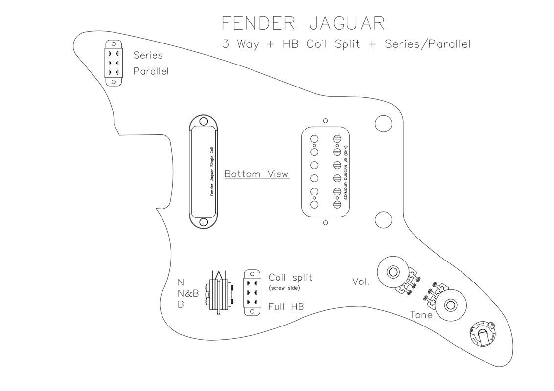
I thank in advance anyone who will help out