I'm wondering if anyone could help me modify a Bally Say it Again board to have a delay time and feedback control. This is a delay effect board that is used in a pinball machine that's running a Reticon SAD4096. The board has a regeneration control but the max and min settings sound pretty much the same and the delay time is fixed.
Schematic link...
Here's what the board effect sounds like (not mine): https://www.youtube.com/watch?v=aHzfHYGZ69U
Anyone REALLY know analog delay circuits inside and out? Need help with a mod
-
Jay

- Admin

- Posts: 7718
- Joined: Mon Sep 11, 2006 5:01 pm
- Location: Santa Ana, CA
- Contact:
-
fuzzjunkie

- Expat

- Posts: 7299
- Joined: Thu Oct 12, 2006 11:32 am
- Location: Seattle
Re: Anyone REALLY know analog delay circuits inside and out? Need help with a mod
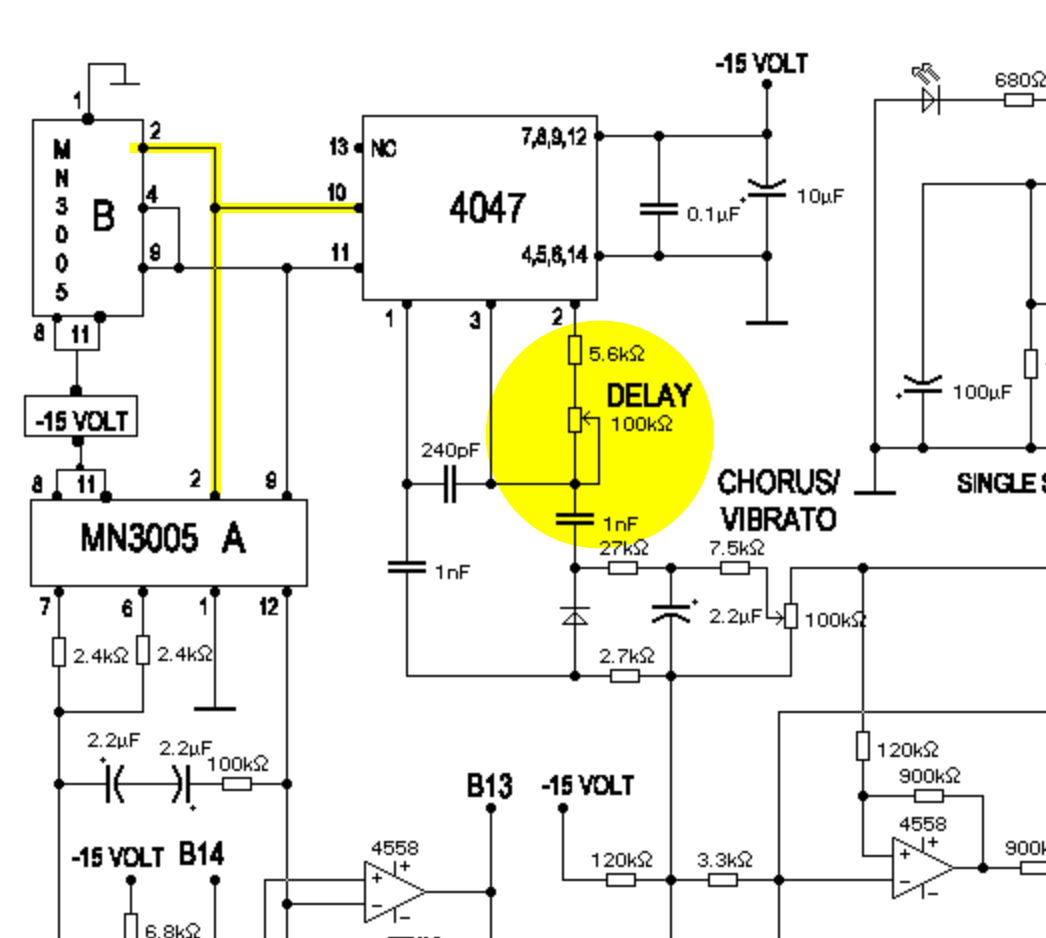
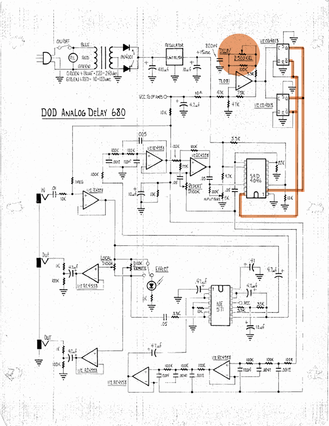
I looked at the DOD 680 delay schematic; because they used the same chip, but didn't find anything helpful other than its a rare and expensive IC to replace.
For the delay time it looked like the resistor coming off pin 3 could be replaced with a pot, but I don't know which one. Initially I thought the first one off pin 14, before the bias, but then I looked at the DOD and it was routed differently. I couldn't find a pin out diagram for the SAD4096, so no help there either, but it looks like pin 14 is the in and pin 3 starts the bucket brigade line? It looks like the feedback range is fixed by a resistor (R2), but not sure if removing it or increasing the pot value (50k seems enough) would give it more range or not. Maybe the capacitator feeding the pot is shot?
So, more of a bump than anything.
-
fuzzjunkie
- Expat
- Posts: 7299
- Joined: Thu Oct 12, 2006 11:32 am
- Location: Seattle
Re: Anyone REALLY know analog delay circuits inside and out? Need help with a mod
So, a Memory Man uses a different chip, but it has a topography that is closer than the DOD, and the Delay pot is off pin 3. It is between what is R17 and C23 off pin 3 on this Bally schematic and opposite the bias part of the circuit, just like it is here. That was my 1st impression and seems like it might be true here? The feedback loop is much simpler and in a completely different place than any I have seen before though.
-
fuzzjunkie
- Expat
- Posts: 7299
- Joined: Thu Oct 12, 2006 11:32 am
- Location: Seattle
Re: Anyone REALLY know analog delay circuits inside and out? Need help with a mod
So, one last bump. I got tired of looking at analog delay schematics and started looking at Pinball Forums for Say it Again mods. It seems that the SAD4096 chip is notorious for crapping out : you probably already know this : a couple of guys make replacement boards for the Centaur because the Sqwauk and Talk still works but sounds lame without echo and reverb.
A couple of them make boards with pots for delay time and feedback control. They are simpler boards than the Say it Again and use a different chip, but maybe one of them can give you an idea if the chip still works.
The other thing is a repair guy who rebuilds boards for all the Bally machines says that the feedback looses range when the Bias drifts, so try that trimmer, or there is a battery sized capacitator that he always replaced wether it worked or not because it was a matter of time like the chip, before failure.
Cheers. I was bored and curious.
-
Jay
- Admin
- Posts: 7718
- Joined: Mon Sep 11, 2006 5:01 pm
- Location: Santa Ana, CA
- Contact:
Re: Anyone REALLY know analog delay circuits inside and out? Need help with a mod
So I already hooked up the scope and set the bias properly. It had definitely drifted but the circuit works fine outside of being noisy (expected) and having some clock noise bleeding into the audio (annoying). I know all about the other boards and have read through all the technical docs on the Bally stuff. I'm fixing pinball machines full time these days so I need to know how this stuff works. This delay board though, this is more for me and my own knowledge. I could spend $85 to replace the entire board with the small and well designed digital delay replacement (what I would advise a customer to do) but I'd love to keep the real analog board in mine for now. I also replaced all the electros... 3 of 4 were failing so might as well. Didn't do squat for the noise issues unfortunately.
I managed to mod the circuit to increase the feedback control (labeled resonance, changed to a 270k fixed resistor and 1M trim pot) and I also added a mix control trimmer to the board (replaced R31 with a 1M trim pot) so I can get some really intense stuff going on now but I think it would be neat to have longer or shorter delay times to play around with and I'd love to be able to publish these mods for those that might want to fuss with theirs.
Here's the Reticon datasheet:
http://offsetguitars.com/personal/jay/sayitagain.pdf
When I'm looking at other delay schematics it appears the delay time is set at the front end of the clock circuit, usually around a transistor or opamp, prior to the logic device that sets the clock frequency... or something like that anyway. Both the MXR Time Delay and the DOD 680 do this. The Say it Again board doesn't have a small amplifier circuit prior to the clock unless I'm misunderstanding. A STRONG possibility since I'm not remotely knowledgeable outside of troubleshooting generally.
Examples...
-
Jay
- Admin
- Posts: 7718
- Joined: Mon Sep 11, 2006 5:01 pm
- Location: Santa Ana, CA
- Contact:
Re: Anyone REALLY know analog delay circuits inside and out? Need help with a mod
In case anyone is interested... changing the voltage at the input to U5 adjusts the clock frequency and alters the delay time so I put a 250k pot in. Unfortunately, the clock signal gets really loud as the delay time gets longer (and the frequency goes down). It does get less audible as the frequency goes up however, so it's nice to get the times shorter and get more of a true reverb effect with a bit less noise overall. 
-
fuzzjunkie
- Expat
- Posts: 7299
- Joined: Thu Oct 12, 2006 11:32 am
- Location: Seattle
Re: Anyone REALLY know analog delay circuits inside and out? Need help with a mod
You are doing a deep dive. I didn't know if you were repairing a board or trying to convert into a delay pedal.
I does seem to be set up more as a reverb than an echo and I noticed the same thing about the configuration. I was wondering why U5 didn't run back to U2 and thought if it did you could put a 100k pot along with a resistor and capacitator off of, I forget which pin and back to U2 like it would run on a Memory Man. There seems to be plenty of filtering. I wonder why the clock noise is so bad? You can expect some with increasing the delay time, but It shouldn't be as obvious with delays as short as this?
Maybe a mod like the Memory Man (I think the Boss DM-2 is like that as well) instead of a voltage control? You might be overdriving the chip along with increasing the delay time? Or perhaps a 100k rather than 250k? Interesting solution though!
-
fuzzjunkie
- Expat
- Posts: 7299
- Joined: Thu Oct 12, 2006 11:32 am
- Location: Seattle
Re: Anyone REALLY know analog delay circuits inside and out? Need help with a mod
I've only dug into schematics for my old UE-400 and 405 and Yamaha E-1010 to tweak them, but after looking at some circuits here:
http://experimentalistsanonymous.com/di ... 0Samplers/
Previously I thought R38 might be replaced with a 100k pot. I found a circuit that uses different chips but has a similar layout to your Bally and it has a 20k pot for delay time adjustment from 50-150ms in the equivalent spot as R38 on Say it Again board. That is a reverb to slapback length, but take a look at the 5k analog delay module, the Bally has more in the way of filtering but look at the way the chips interact/tie together, very similar.
-
Jay
- Admin
- Posts: 7718
- Joined: Mon Sep 11, 2006 5:01 pm
- Location: Santa Ana, CA
- Contact:
Re: Anyone REALLY know analog delay circuits inside and out? Need help with a mod
I just grabbed a 250k since it would let me go both ways in resistance to see what would happen. And it did just that... the only touble is when going longer that clock frequency becomes very very loud. I think the only thing left to do is figure out a place for a simple low pass filter that might cut anything below 2 or 3khz. I tried putting one right on the output but it killed all my volume and seemed to be cutting way below what the calculator said.
-
fuzzjunkie
- Expat
- Posts: 7299
- Joined: Thu Oct 12, 2006 11:32 am
- Location: Seattle
Re: Anyone REALLY know analog delay circuits inside and out? Need help with a mod
I think you mean high pass filter? When you want to cut the lower frequencies. But most BBD circuits have LPFs going in and on the output between each IC.
On the SAD4096, I finally found a pin out diagram and which pins were the clock, etc, and a bit more info.
* I was wondering why the schematic for my E1010 had each IC listed as a "4096 BBD" when they are clearly MN3005s ( Four, one for each stage, and a 512 for the first sub 10ms delay), and found that 4096 is the max number of stages or "buckets " in each BBD, so the MN3005 is a 4096 stage chip like the SAD4096, while the SAD512, has 512 = Doh! *
Anyway, the E1010 is a hi-fi analog delay and barely pushes the chip limits with four stages maxing out at 300ms. Some devices, dark, murky, noisy devices, have one 4096 for 600-800ms.
The SAD4096 needs a low impedance 2-phase clock drive, since its clock terminal input capacitance is about 1000pF. Some chips are 2-phase, others are 4-phase. The clock frequency runs 8-1000 kHz for 2-250ms of delay time. Ideal clock range yields delay times 102.4ms at 7kHz over 4096 stages and 250ms at 3kHz. Not sure if you can measure for that or if you need sophisticated equipment?
Sounds like the MXR and DOD delays are way overclocked! I have an old AD/A Flanger and some of the early ones used the SAD4096, I think mine is a little later though, but it seems for hi-fi delays you'd want multiple ICs, otherwise it's better for flanger or chorus effects. How long of a delay are you getting when the clock noise starts to get loud?
-
Jay
- Admin
- Posts: 7718
- Joined: Mon Sep 11, 2006 5:01 pm
- Location: Santa Ana, CA
- Contact:
Re: Anyone REALLY know analog delay circuits inside and out? Need help with a mod
I did mean low pass filter. The goal was to see if I could create a low pass that would leave the clock noise well above the bandpass and so inaudible. I think you're math is good though as the longer delay times (getting near 300ms if I were to guess) bring some pretty serious howl into the mix. I could see it easily being in lower than 1k. A low pass filter to get rid of that isn't likely to sound very good. I'm probably going to quit messing with it at this point as I'm happy with where it's at. I'll post a video this weekend if I get a chance.